
Miniature carrier system for cryopreservation of biological materials, bucket and cryopreservation method

A carrier system and biomaterial technology, applied in the field of micro-carrier systems, can solve the problems of assisted reproductive institutions, inconvenient operation, inability to meet large-scale sample cryopreservation and development, etc.

Active Publication Date: 2013-12-18
吕祁峰
View PDF8 Cites 14 Cited by
  • Summary
  • Abstract
  • Description
  • Claims
  • Application Information

AI Technical Summary

Problems solved by technology

For a large-scale assisted reproductive center, if the average monthly egg retrieval cycle exceeds 500, even if the space released by thawing embryos is taken into account, the liquid nitrogen tank required for adding frozen embryos may cost an average of Adding one will cause a large space occupation in a few years
This limits the development of an assisted reproductive facility
Therefore, the space utilization efficiency of the current micro-biological sample freezing device and its corresponding loading technology is relatively low, and it is still unable to meet the needs of large-scale sample cryopreservation and its development.
[0007] On the other hand, during the freezing or thawing operation, the aluminum alloy material of the rod holder in the liquid nitrogen vapor mist is more likely to condense the water vapor in the air and freeze than other plastic materials, which often causes the label part to be exposed to the liquid nitrogen for a certain period of time. Covered by condensed ice, causing inconvenience in operation

Method used


Image

  • Miniature carrier system for cryopreservation of biological materials, bucket and cryopreservation method
  • Miniature carrier system for cryopreservation of biological materials, bucket and cryopreservation method
  • Miniature carrier system for cryopreservation of biological materials, bucket and cryopreservation method

Examples


Embodiment 1

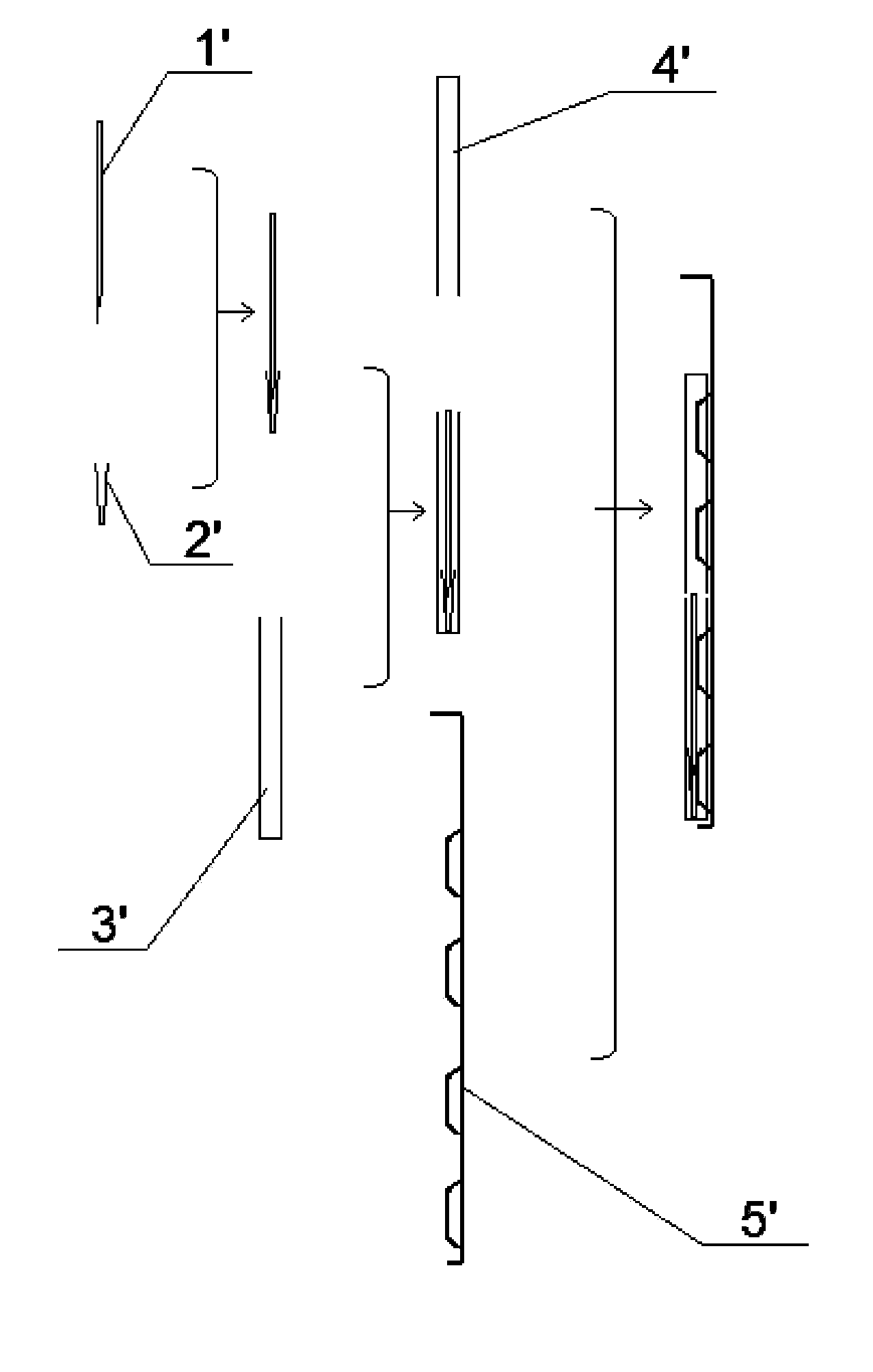
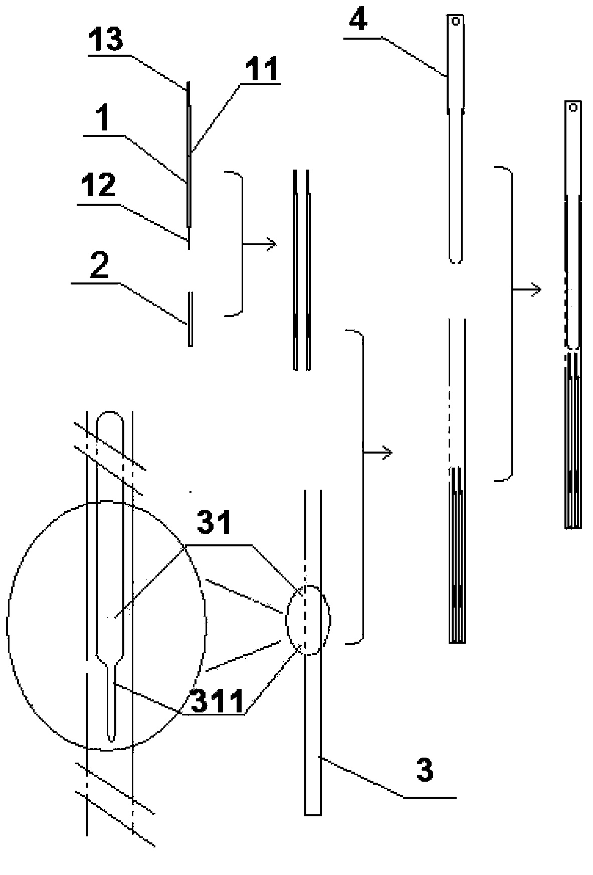
[0077]In this embodiment, the original one-end-opened rod-loading tube 3' is changed into a thinner and elongated rod-loading tube with an elongated window from the side, that is, notch 31 (rod loading opening), and at least a closed bottom end. 3. The loading and unloading of the loading rod in the loading rod tube is carried out from the side notch 31 through tweezers; the external force clamping type loading rod cap 4' is discarded, and the lower section is inserted into the loading rod from the top opening of the loading rod tube. The stop rod 4 fixed by friction in the rod barrel controls the opening length of the notch 31 by the length of the stop rod at the notch 31. When the opening is long, the loading rod 1 (loading unit) can be picked and placed. , when the opening is shorter, the sliding of the loading rod 1 in the loading rod tube 3 can be blocked. This eliminates the need for an external rod-carrying cap, thereby correspondingly abandoning the rod-carrying holder...

Embodiment 2

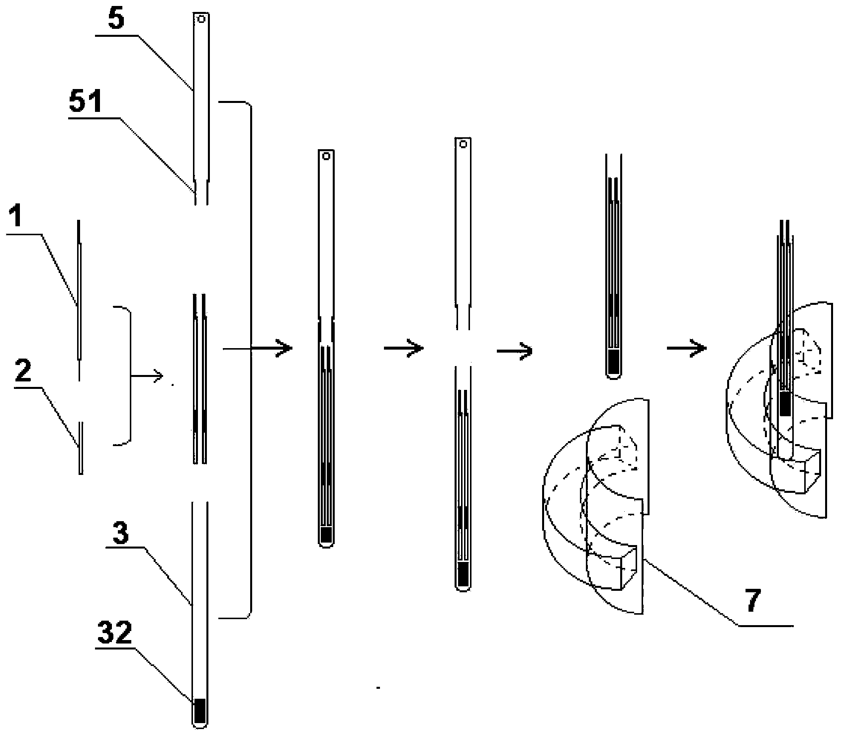
[0092] In this embodiment, the original one-end-opened rod-loading tube 3' is changed into a thinner and elongated one that opens from the top, that is, the opening of the rod-loading tube, and the bottom end is closed, and a movable iron block is placed at the bottom of the tube. Rod tube 3; the removal of the loading rod in the loading rod tube is: through the magnetic positioning concave seat, the movable iron block is driven up to raise the loading rod to expose the top loading rod tube opening; the external force clamping type loading rod cap is discarded The cover 4' is changed to a sleeve 5 with a lower connecting section that can be inserted into the rod-loading tube from the mouth of the rod-loading tube and fixed by friction, so as to close the rod-loading port and extend the cryopreservation unit to a length beyond the depth of the bucket of the liquid nitrogen tank . Thereby, the rod-loading tube holder for clamping the rod-loading tube cap that takes up the most s...

Embodiment 3

[0104] In the microcarrier system provided by the present invention, since the rod-loading tube is thinner, the amount of liquid nitrogen in the rod-loading tube is small during freezing storage, and the liquid nitrogen in the bucket is quickly leaked through the bottom mesh when the bucket is extracted. This makes a small amount of liquid nitrogen in the loading rod tube in a non-liquid nitrogen environment and is easy to completely volatilize. At this time, the frozen storage part of the biological material may not be in the protection of liquid nitrogen, which may easily cause abnormal thawing of the biological material and make the frozen storage fail.

[0105] refer to Figure 4 with 5 , the existing bucket 8' is closed with a side wall, and the bottom is provided with a mesh liquid hole 81'. This embodiment provides a side leakage bucket 8 suitable for storing miniature refrigeration units. The bottom of the bucket is In a closed shape, a liquid hole 81 is provided on ...


PUM

PropertyMeasurementUnit
Outer diameteraaaaaaaaaa
The inside diameter ofaaaaaaaaaa

Abstract

The invention provides a miniature carrier system for cryopreservation of biological materials and application of the carrier system. The miniature carrier system is mainly composed of a cryopreservation unit comprising a carrying pole, a carrying pole sleeve and a carrying pole cylinder, wherein the front end of the carrying pole is inserted into the carrying pole sleeve to form a flat and slender carrying unit, and then the carrying pole and the carrying pole sleeve are arranged in the carrier pole cylinder together; the carrier pole cylinder is a hollow pipe with the average outer diameter of less than 8.5mm, and at least the bottom end of the hollow pipe is closed; the top end or the side wall of the carrier pole cylinder is provided with a pole loading hole, through which a locating unit can be placed in and taken out of the carrier pole cylinder, and loading protection and unloading technologies are implemented by virtue of the pole loading hole. On the basis of not influencing and even improving the use convenience of the miniature carrier system, space occupied for cryopreservation of a trace biological sample is reduced in multiples, and thus a floor space for cryopreservation is saved greatly. The miniature carrier system is especially suitable for cryopreservation of the trace biological materials such as embryos.

Description

technical field [0001] The invention relates to a micro-carrier system for cryopreservation of biological materials, in particular to a set of sample loading devices used for vitrification or other freezing of trace biological materials in the field of biology and medicine and its application. Background technique [0002] At present, there are many kinds of known cryocarrier systems, which can be divided into two types: cryopreservation tube type and cryopreservation rod type according to the main loading unit. The former is usually a cylindrical or partially cylindrical tubular container, one end of which is a blind end, and the other end is closed by a cap in the form of a screw thread or a buckle. This kind of container is usually relatively large, with a volume of more than 1 milliliter, and is mostly loaded and stored in a grid box on a layered carrier of a liquid nitrogen tank. Most of the current cell cryopreservation adopts this form; the latter is a rod-shaped dev...

Claims


Application Information

Patent Timeline
IPC IPC(8): A01N1/02
Inventor 吕祁峰
Owner 吕祁峰
Learn More