Electronic dust remover

An electrostatic precipitator and negative electrode technology, which is applied in the direction of external electrostatic separator, electrode structure, electrostatic separation, etc., can solve the problems of high operating cost of bag filter, large operating resistance of bag filter, and no electrostatic effect. , to achieve the effect of low cost, good high temperature tolerance and long service life

Inactive Publication Date: 2013-12-18
WUHAN LONGKING ENVIRONMENTAL PROTECTION TECH
View PDF10 Cites 24 Cited by
  • Summary
  • Abstract
  • Description
  • Claims
  • Application Information

AI Technical Summary

Problems solved by technology

However, the running resistance of the bag filter is large, and the power of the induced draft fan matched with the bag filter is required to be large, so that the operating cost of the bag filter is high; at the same time, the life of the filter bag on the bag filter is limited, and it is necessary to replace the filter bag The required cost is high; finally, the bag filter has poor tolerance to high-temperature flue gas, and has strict requirements on the moisture content and oil content in the flue gas
[0006] Electric bag filter is widely used in our country at present, but it is found in practice that once the dust leaves the electric field, the recombination speed of the dust will be very fast, and the dust will not produce positive factors of electrostatic effect in the filter bag area.

Method used


Image

  • Electronic dust remover
  • Electronic dust remover
  • Electronic dust remover

Examples


Embodiment Construction

[0033] The implementation of the present invention will be described in detail below in conjunction with the accompanying drawings, but they do not constitute a limitation to the present invention, and are only examples. At the same time, the advantages of the present invention are explained to make the present invention clearer and easier to understand.

[0034] For the convenience of description, the present invention starts with Figure 1 to Figure 6 The illustrated embodiment is taken as an example to illustrate the invention in detail:

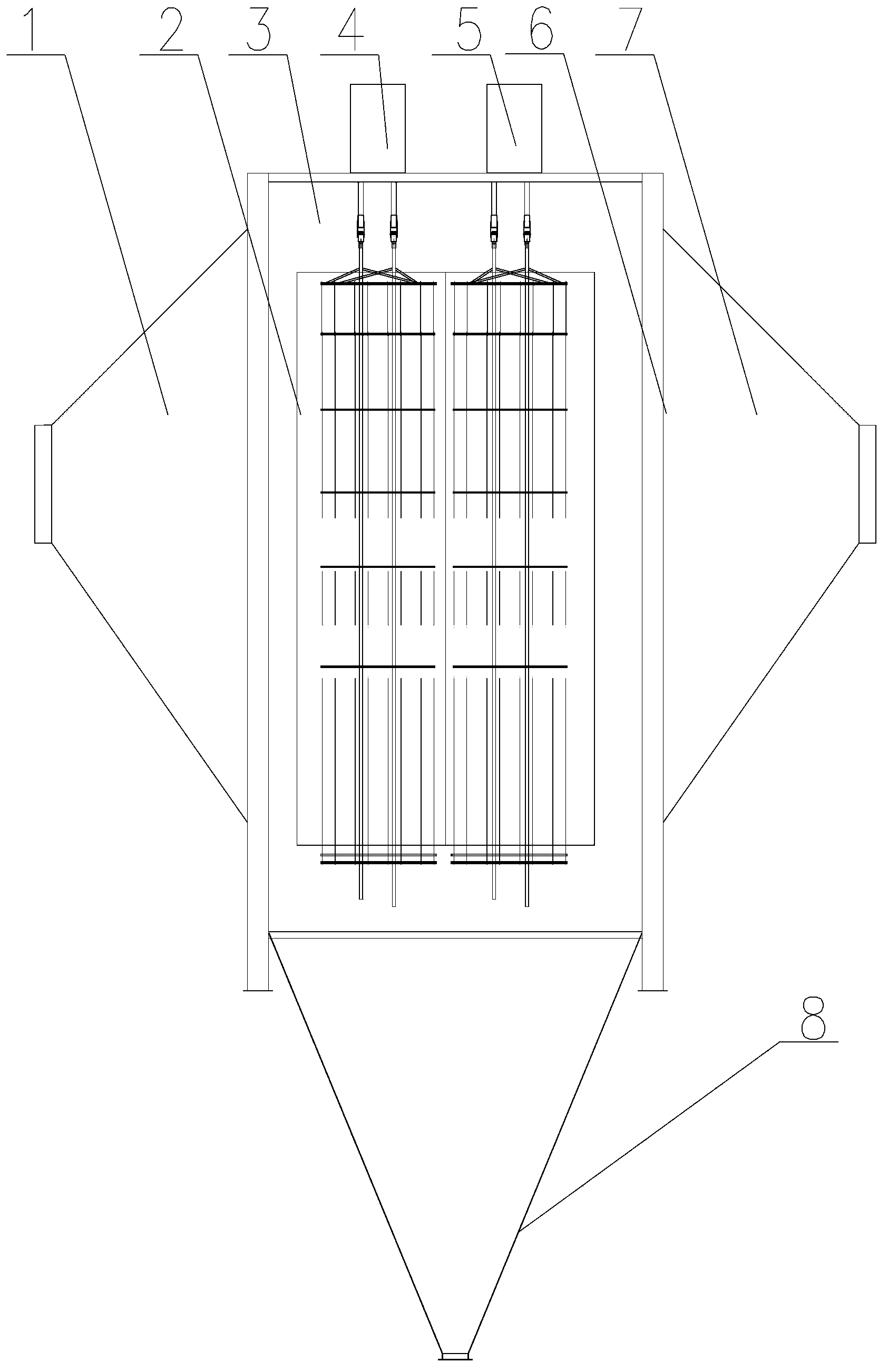
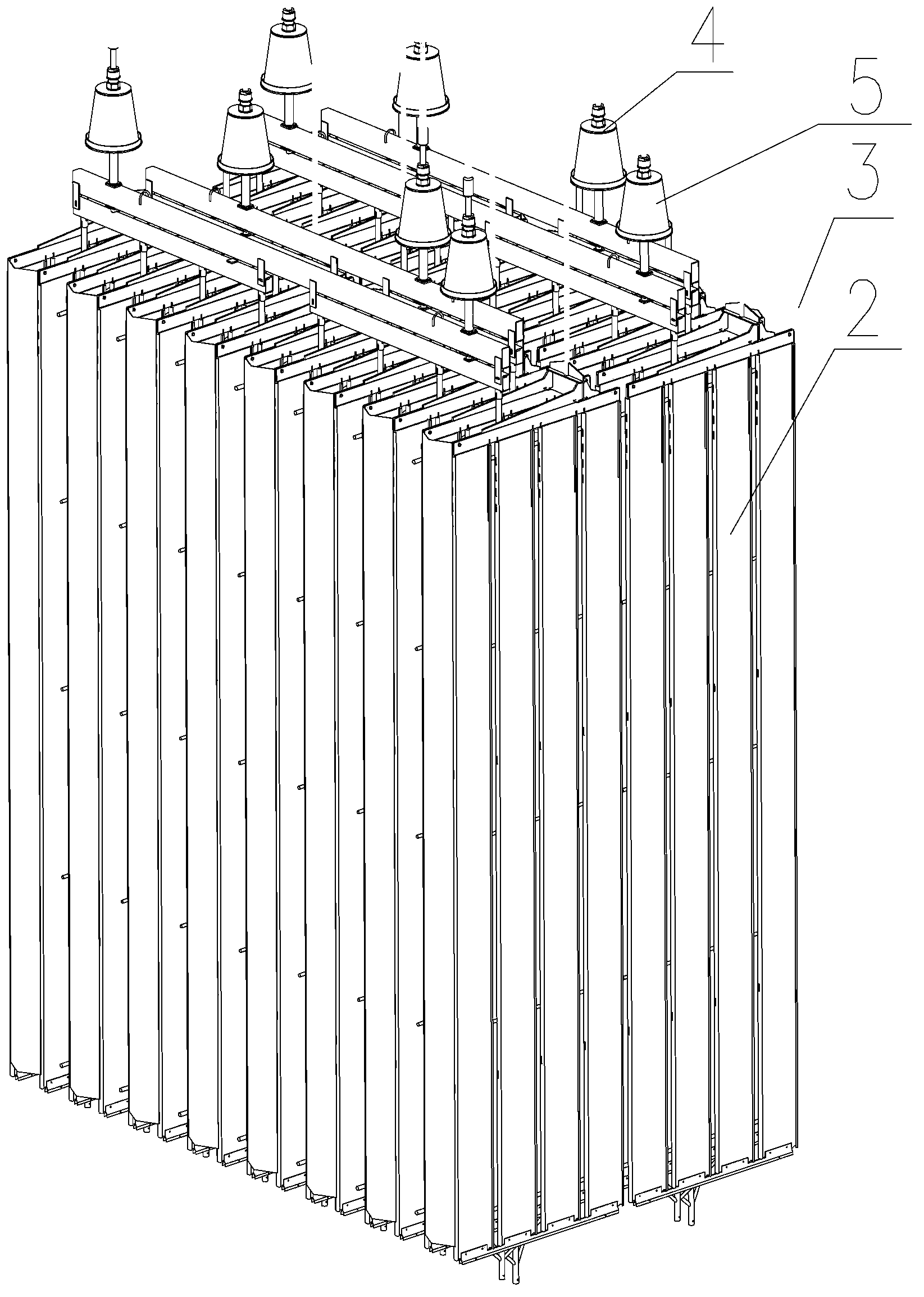
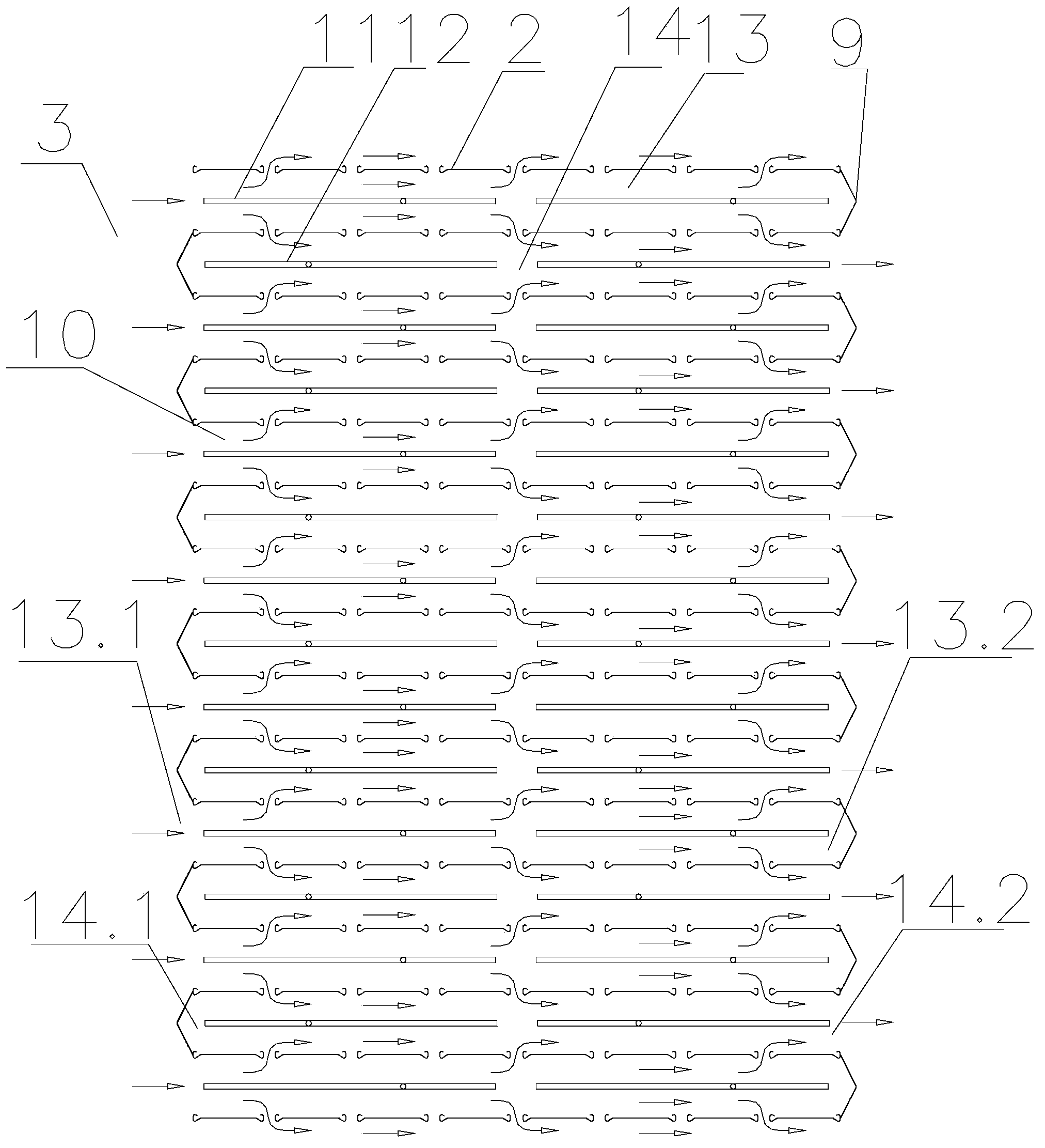
[0035]With reference to the accompanying drawings, it can be seen that the electrostatic precipitator includes a housing 6 with a dust removal cavity 3 inside, one side of the housing 6 communicates with the air intake device 1, and the other side communicates with the exhaust device 7, and the dust removal cavity 3 is provided with a multi-layer grounded dust collection pole 2. The dust collection cavity 3 is divided into a plurality of...


PUM

PropertyMeasurementUnit
Spacingaaaaaaaaaa

Abstract

The invention discloses an electronic dust remover. The electronic dust remover comprises a shell (6) internally provided with a dust removing cavity (3), wherein multilayer grounded dust collection poles (2) are arranged inside the dust removing cavity (3); via the dust collection poles (2), the dust removing cavity (3) is divided into a plurality of smoke channels (10) which are arranged in parallel; an electrode is arranged inside each smoke channel (10); the electrodes in the two adjacent smoke channels (10) are respectively of a positive electrode (11) electrically connected with a positive power source (4) and a negative electrode (12) electrically connected with a negative power source (5); the both ends of the plurality of smoke channels (10) which are arranged in parallel are provided with wind screens (9) for blocking the end parts of the smoke channels (10) at intervals respectively; the wind screens (9) at the both ends of the plurality of smoke channels (10) which are arranged in parallel are arranged in a staggered manner. The electronic dust remover provided by the invention has the advantages of low cost, long service life, convenience in maintenance and good high-temperature tolerance. The defect that the dust removing property of a conventional electronic dust remover is greatly influenced by physical and chemical properties of dust can be overcome; therefore, not only can the dust be unlikely to release from an electric field, but also the composite efficiency of the dust is low.

Description

technical field [0001] The present invention relates to a dust removal equipment, specifically an electric dust collector, which includes a housing with a dust removal cavity inside, one side of the housing communicates with an air intake device, and the other side communicates with an exhaust device, so There are multi-layer grounded dust collection poles in the dust removal cavity, and the dust removal cavity is divided into a plurality of flue gas passages arranged in parallel by the dust collection poles. One end of the flue gas passage corresponds to the air intake device, and the other end corresponds to the exhaust Air device correspondence Background technique [0002] At present, the main dust removal equipment for treating flue gas containing dust is electrostatic precipitator, bag filter, and electric bag composite dust collector. [0003] The electrostatic precipitator is equipped with a high-voltage electric field area in the dust-removing cavity of the shell, ...

Claims


Application Information

Patent Timeline
IPC IPC(8): B03C3/08B03C3/34B03C3/47B03C3/40
Inventor 李军张会君王飞别攀明平洋李宁
Owner WUHAN LONGKING ENVIRONMENTAL PROTECTION TECH
Why Eureka
Try Eureka