
Optical anti-fake element and production method thereof

An optical anti-counterfeiting and component technology, applied in optical components, optics, diffraction gratings, etc., can solve problems affecting anti-counterfeiting effects, color differences, increasing process complexity and cost, etc.

Active Publication Date: 2013-12-18
ZHONGCHAO SPECIAL SECURITY TECH +1
View PDF8 Cites 22 Cited by
  • Summary
  • Abstract
  • Description
  • Claims
  • Application Information

AI Technical Summary

Problems solved by technology

However, in actual production, it is usually difficult to precisely control the coating thickness of the above-mentioned interferometric optically variable anti-counterfeiting elements to meet the requirements of color matching, resulting in obvious differences in color at the designed matching angle, which affects the anti-counterfeiting effect
In addition, the two coatings cannot be obtained in one evaporation process, so it is necessary to increase the precise positioning of printing protective glue, demetallization, and secondary evaporation of optically variable coatings, which increases the complexity and cost of the process.

Method used


Image

  • Optical anti-fake element and production method thereof
  • Optical anti-fake element and production method thereof
  • Optical anti-fake element and production method thereof

Examples


Embodiment Construction

[0021] The optical anti-counterfeiting element and the manufacturing method thereof according to the present invention will be described in detail below with reference to the accompanying drawings.

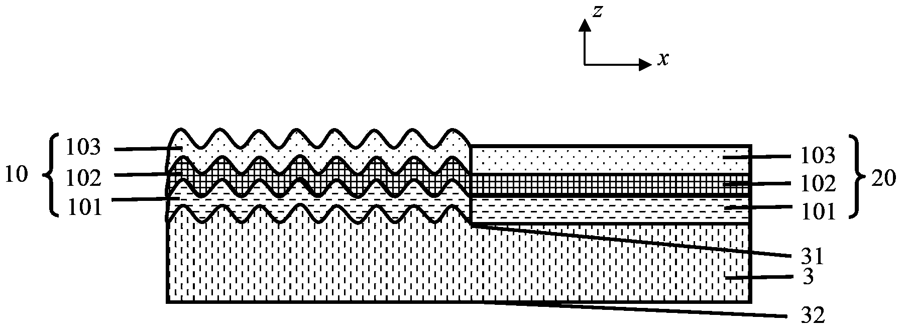
[0022] like figure 1 As shown, the optical anti-counterfeiting element according to an embodiment of the present invention includes a substrate 3, the substrate 3 includes a first surface 31 and a second surface 32, and a partial area on the first surface 31 is subwavelength micro-relief Structure, partial area is flat surface structure. A first dielectric layer 101, a second dielectric layer 102 and a third dielectric layer 103 are sequentially stacked on the sub-wavelength micro-relief structure and the flat surface structure area, thereby forming the interference structures 10 and 103 located in the sub-wavelength micro-relief structure area, respectively. The interference structure 20 in the region of the flat surface structure. in, figure 1 The coordinate z in represents t...


PUM

PropertyMeasurementUnit
Thicknessaaaaaaaaaa
Thicknessaaaaaaaaaa
Thicknessaaaaaaaaaa

Abstract

The invention provides an optical anti-fake element and a production method thereof, aiming to overcome defects that processes in the prior art are complicated and it's difficult to realize color matching due to difficulty in accurately controlling thickness of coating layers of two types of coating structures in the prior art. The optical anti-fake element comprises a substrate (1) consisting of a first surface (31) and a second surface (32). Part of the first surface (31) is of a sub-wavelength micro-relief structure while another part thereof is of a flat surface structure; a first medium layer, a second medium layer and a third medium layer are sequentially superposed on the sub-wavelength micro-relief structure and the flat surface structure; colors of the sub-wavelength micro-relief structure and the flat surface structure are the same when observed in specific viewing angle, and are different when observed in other angles.

Description

technical field [0001] The invention relates to the field of optical anti-counterfeiting, in particular to an optical anti-counterfeiting element and a preparation method thereof. Background technique [0002] Because the optically variable coating can present different colors under different viewing angles, it is easy to describe, easy to identify by the public, and cannot be imitated or copied by electronic equipment such as cameras, scanners, printers, etc., so the optically variable coating has high anti-counterfeiting ability. It is widely used in the public anti-counterfeiting of high anti-counterfeiting securities such as banknotes. [0003] In order to improve the anti-counterfeiting capability of the optically variable coating, the prior art mostly combines two optically variable coatings to achieve two optically variable effects. For example, US5766738, US6114018 and US7729026 propose interference optically variable anti-counterfeiting elements that can achieve op...

Claims


Application Information

Patent Timeline
IPC IPC(8): B42D25/324G02B5/18
CPCG02B5/1809G02B5/1823
Inventor 张巍巍王晓利孙凯
Owner ZHONGCHAO SPECIAL SECURITY TECH
Learn More