Length detection and automatic feeding and discharging device for short metal bar stocks

A technology of feeding and discharging materials and short bars, applied in conveyor control devices, transportation and packaging, conveyors, etc., can solve problems such as increasing product rejection rate, affecting forging accuracy and quality, and inconsistent heating temperature, ensuring continuity and The effect of stability, improving forging accuracy and high degree of automation

Inactive Publication Date: 2013-12-18
XUZHOU HAODING MACHINERY
View PDF6 Cites 13 Cited by
  • Summary
  • Abstract
  • Description
  • Claims
  • Application Information

AI Technical Summary

Problems solved by technology

[0002] At present, in the forging production line, through the transmission of the chain, the short metal bars arranged on the chain will enter the heating furnace for heating, and the length detection and automatic distribution of the short metal bars cannot be carried out during the transportation process. The influence of the shearing machine in the first process, during the cutting process, the length of the short metal bar will vary, and the length is not the same. The front part of another bar that follows it will also be mixed in with the transmission direction of the chain, and the length of the short metal bar will be unqualified, which not only increases the product rejection rate, but sometimes causes the automatic feeding and discharging device jamming, forcing the production line to stop, resulting in wasted energy and reduced output
In the past, in the conveying process of metal short bars, wastes with unqualified lengths were manually removed based on experience, and the delivered short bars were manually pushed into the material rail, so that there was a certain gap between the front and rear short bars. This approach not only requires high personnel, but also the heating time of the metal short bar is not fixed, resulting in inconsistent heating temperature, affecting the forging precision and quality, resulting in waste of manpower and resources

Method used


Image

  • Length detection and automatic feeding and discharging device for short metal bar stocks
  • Length detection and automatic feeding and discharging device for short metal bar stocks
  • Length detection and automatic feeding and discharging device for short metal bar stocks

Examples


Embodiment Construction

[0015] The present invention will be further described below in conjunction with accompanying drawing.

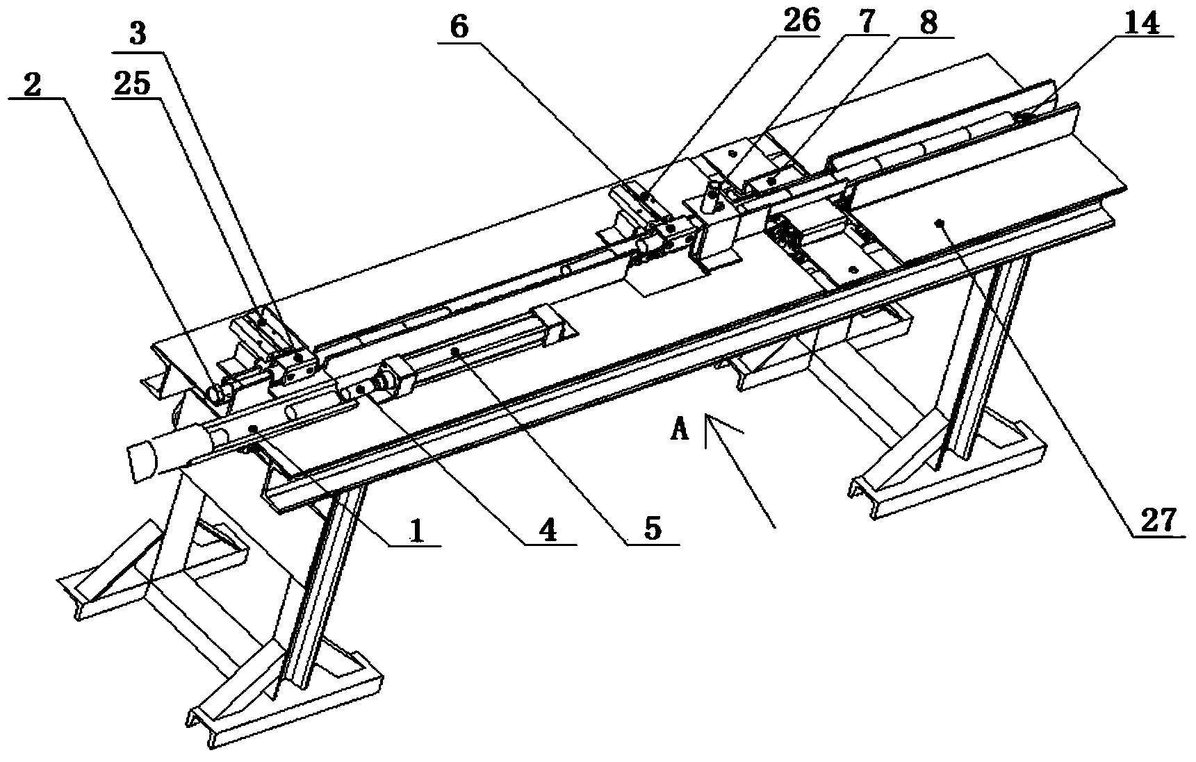
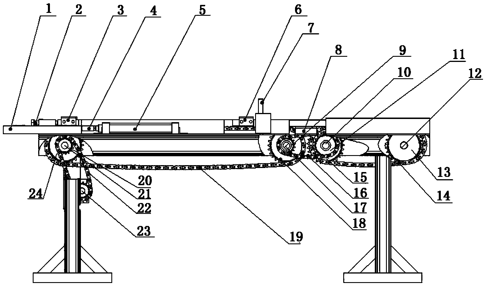
[0016] by figure 2 The one shown on the right is the front for description, such as figure 1 , figure 2 with image 3 As shown, the present invention comprises support 27, material rail 1, motor driving wheel 20, motor driving wheel 23, transmission chain-22, longitudinal cylinder 5, primary driven wheel 13, secondary driving wheel 24, transmission shaft-12, transmission Shaft four 21 and bearing seat 28, the material rail 1 is arranged on the support 27, the motor driving wheel 20 and the motor driving wheel 23 are connected by the transmission chain one 22, and the longitudinal cylinder 5 is arranged in front of the material rail 1 and is in the same position as it. On the axis, the longitudinal cylinder push plate 4 is fixed on the extended end of the longitudinal cylinder 5, and the transmission shaft one 12 and the transmission shaft four 21 are installed on the t...


PUM


Abstract

The invention discloses a length detection and automatic feeding and discharging device for short metal bar stocks, and belongs to the technical field of mechanical bar stock conveying devices. A transition plate (8) is arranged between a primary chain (14) and a secondary chain (19). A length sensor (7) is arranged above the secondary chain (19). A screening cylinder (26) is fixedly arranged on a bracket (27) on one side of the secondary chain (19), and is perpendicular to the secondary chain (19). A screening cylinder pushing plate (6) is fixedly arranged at the extending end of the screening cylinder (26). A transverse cylinder (25) is arranged on one side of the rear part of the secondary chain (19), and is perpendicular to the secondary chain (19). A transverse cylinder pushing plate (3) is fixedly arranged at the extending end of the transverse cylinder. According to the device, the transition plate, the length sensor, the screening cylinder, the screening cylinder pushing plate, the transverse cylinder, the transverse cylinder pushing plate, a longitudinal cylinder and a longitudinal cylinder pushing plate are additionally arranged, so that the heating continuity and stability of the short metal bar stocks are improved, the forging and pressing accuracy is improved, and high automation degree is ensured.

Description

technical field [0001] The invention relates to a length detection and automatic feeding and discharging device, in particular to a short metal rod length detection and automatic feeding and discharging device, which belongs to the technical field of mechanical conveying rods. Background technique [0002] At present, in the forging production line, through the transmission of the chain, the short metal bars arranged on the chain will enter the heating furnace for heating, and the length detection and automatic distribution of the short metal bars cannot be carried out during the transportation process. The influence of the shearing machine in the first process, during the cutting process, the length of the short metal bar will vary, and the length is not the same. The front part of another bar that follows it will also be mixed in with the transmission direction of the chain, and the length of the short metal bar will be unqualified, which not only increases the product rej...

Claims


Application Information

Patent Timeline
Patent Type & Authority Applications(China)
IPC IPC(8): B65G17/26B65G47/82B65G47/26B65G43/08
Inventor 胡森刘三元刘峰
Owner XUZHOU HAODING MACHINERY
Why Eureka
Try Eureka