
Special hoisting arrangement structure for allowing aluminum strip annealing coil to enter or exit high rack warehouse

A technology of high-bay warehouse and layout structure, applied in the field of production material transportation, can solve the problems such as the inability to store the annealing furnace storage table, the high risk factor of the workshop crane, and the impact on production and transportation, so as to facilitate centralized ventilation treatment, reduce plant cost, Easy to operate effect

Active Publication Date: 2013-12-18
CHINA NON-FERROUS METALS PROCESSING TECH CO LTD
View PDF4 Cites 0 Cited by
  • Summary
  • Abstract
  • Description
  • Claims
  • Application Information

AI Technical Summary

Problems solved by technology

According to the conventional design, the workshop crane is usually arranged along the parallel direction of the annealing span of the finishing workshop, and its running distance is long, resulting in a high risk factor in the long-distance transportation process of the workshop crane when lifting and transporting the annealing coil. In addition, the heat emitted by the annealing coil has a great impact on the environment of the annealing coil during transportation.
At the same time, in the area close to the end of the high-bay warehouse, there is a "dead zone" that cannot be lifted by the workshop crane, so this area cannot store the annealing furnace storage table, which will have a certain impact on production and transportation

Method used


Image

  • Special hoisting arrangement structure for allowing aluminum strip annealing coil to enter or exit high rack warehouse

Examples


Embodiment Construction

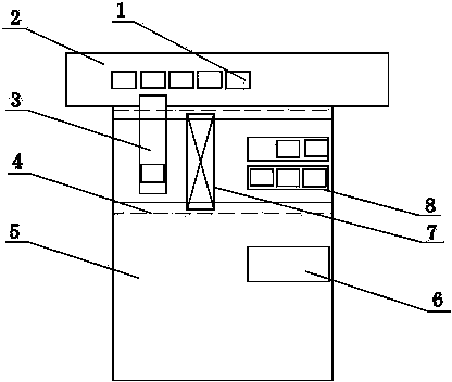
[0014] combine figure 1 , a hoisting layout structure specially used for aluminum strip annealing coils entering and exiting the high-bay warehouse, including a high-bay warehouse 2, an annealing bay 5 and an annealing furnace 6 located in the annealing bay, the high-bay warehouse 2 is arranged adjacent to the side wall of the annealing bay 5, On the side wall of the annealing span 5, there is a passage for the passage of the special material seat 3 for the elevated warehouse 2. One end of the special material seat 3 is located in the elevated warehouse 2, and the other end is located in the annealing span 5, and the other end of the special material seat 3 is connected to the The annealing volume storage platform 8 is located in the same inter-column area 4 within the annealing span 5, the inter-column area 4 is surrounded by the factory building columns supporting the annealing span 5, and a crane 7 is erected above the inter-column area 4, and the crane 7 The running direct...


PUM


Abstract

The invention discloses a special hoisting arrangement structure for allowing an aluminum strip annealing coil to enter or exit a high rack warehouse. The special hosting arrangement structure comprises the high rack warehouse, an annealing span and an annealing furnace located in the annealing span, wherein the high rack warehouse is adjacent to the side wall of the annealing span; the side wall of the annealing span is provided with a passage allowing a special material holder of the high rack warehouse to pass through; one end of the special material holder is located in the high rack warehouse, and the other end of the special material holder is located in the annealing span; the other end of the special material holder and an annealing coil storage platform are located in the same inter-column region in the annealing span; the inter-column region is defined by workshop columns for supporting the annealing span; an overhead traveling crane is erected above the inter-column region; the moving direction of the overhead traveling crane is vertical to the arrangement direction of the annealing span. According to the arrangement structure disclosed by the invention, the annealing coil storage platform and the special material holder of the high rack warehouse in the annealing span are arranged in the same inter-column region, so that the special hoisting arrangement structure is compact in layout and convenient to operate.

Description

technical field [0001] The invention belongs to the technical field of production material transportation in a non-ferrous metal aluminum plate and strip processing workshop, and in particular relates to a hoisting arrangement structure specially used for aluminum strip annealing coils entering and exiting an elevated warehouse. Background technique [0002] The annealing furnace is a production equipment used for annealing of aluminum coils in the aluminum strip processing and finishing workshop. During the cold rolling process of aluminum alloy, as the amount of processing deformation increases, the deformation resistance increases, resulting in work hardening. At this time, intermediate annealing is required to improve the plasticity of the material. When the aluminum alloy reaches the size requirements of the finished product after cold deformation, it is often necessary to perform different annealing treatments for the finished product according to the state requirement...

Claims


Application Information

Patent Timeline
IPC IPC(8): C21D1/00
Inventor 赵晶磊吴双锁苏小新张满友梁延彬
Owner CHINA NON-FERROUS METALS PROCESSING TECH CO LTD
Learn More