Curve drafting device

A drafting device and curve technology, applied in the field of spinning technology, can solve the problems of increasing yarn hairiness, affecting product quality, uncontrollable left and right movement of fiber bundles, etc., and achieve the effect of facilitating forward movement and reducing yarn hairiness

Inactive Publication Date: 2013-12-18
程登木
View PDF11 Cites 1 Cited by
  • Summary
  • Abstract
  • Description
  • Claims
  • Application Information

AI Technical Summary

Problems solved by technology

[0002] In the drafting area behind the ring spinning machine, the friction force of the middle and rear parts is increased. The existing technology is to use a horizontally placed pressure bar to make the fiber bundles bend up and down. It can make the fiber bundles form in the direction of their movement. The upper and lower directions of the plane are constrained. Although this device with only two-dimensional space constraints can play a certain role in improving the friction boundary of the middle and rear parts, it cannot control the left and right movement of the fiber bundles. The fiber bundle will become wider and wider during the drafting process, increasing yarn hairiness and affecting product quality

Method used


Image

  • Curve drafting device
  • Curve drafting device
  • Curve drafting device

Examples


Embodiment Construction

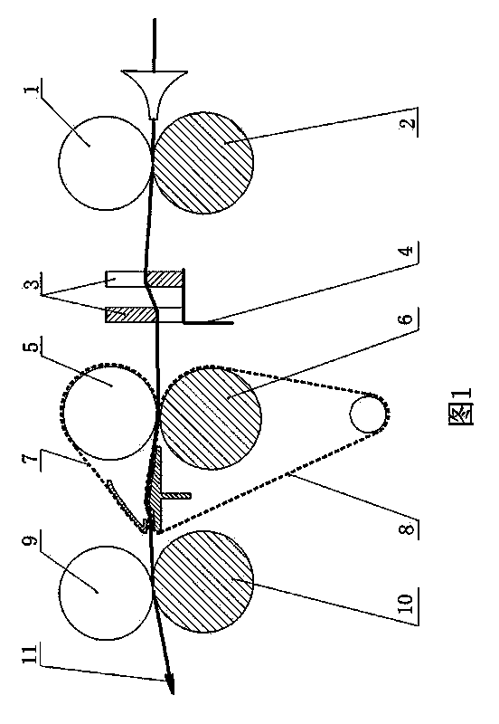
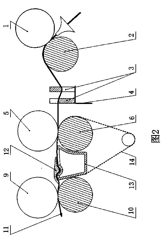
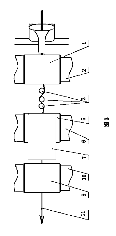
[0018] In the illustration, the surface linear speed of the rear top roller (1) and rear roller (2) < the surface linear speed of the middle top roller (5) and middle roller (6) < the surface speed of the front top roller (9) and front roller (10) The surface linear speed, the positioning body (3) is installed in the drafting area relying on the positioning body support frame (4), when the fiber bundle (11) moves forward under the action of the front traction and passes the positioning body (3), the positioning body (3 ) enables the fiber bundle (11) to pass through the drafting zone from back to front in the form of a three-dimensional curve in space, because when the fiber bundle (11) passes through the positioning body (3), the positioning body (3) can strengthen the fiber bundle (11) in the drafting zone ), which is beneficial to meet the spinning process requirements of "forward, concentrated, and stable" fiber speed change points, and improve the dryness and quality of th...


PUM


Abstract

The invention discloses a curve drifting device applicable to the field of spinning. The curve drafting device structurally comprises a back jaw, a middle jaw, a front jaw and positioning bodies, the back jaw is composed of a back roller and a back-upper roller, the middle jaw is composed of a middle roller and a middle-upper roller, and the front jaw is composed of a front roller and a front-upper roller. Two or more than two positioning bodies are arranged between the jaws of a same spin. A connected line from fiber bundles into a back drafting zone till out of the same shows that the positioning bodies can control fiber bundles to move forward in the form of three-dimensional space curves. By the curve drafting device, friction boundary on the middle-back portions of the drafting zone can be enhanced, fibers are benefited in speed-change point leading forward, collecting and stabilizing, edge fibers of the fiber bundles can be collected, yarn hairiness is reduced, and a three-dimensional space can be accurately positioning during a drafting process of the fiber bundles.

Description

technical field [0001] The invention relates to a spinning technique. Background technique [0002] In the drafting area behind the ring spinning machine, the friction force of the middle and rear parts is increased. The existing technology is to use a horizontally placed pressure bar to make the fiber bundles bend up and down. It can make the fiber bundles form in the direction of their movement. The upper and lower directions of the plane are constrained. Although this device with only two-dimensional space constraints can play a certain role in improving the friction boundary of the middle and rear parts, it cannot control the left and right movement of the fiber bundles. The fiber bundle will become wider and wider during the drafting process, increasing yarn hairiness and affecting product quality. Contents of the invention [0003] The present invention is used to overcome the defects of the prior art and provide a curved drafting device, which is constrained in the...

Claims


Application Information

Patent Timeline
Patent Type & Authority Applications(China)
IPC IPC(8): D01H5/22
Inventor 不公告发明人
Owner 程登木
Why Eureka
Try Eureka