Magnetic transmission piston-type valveless compressor

A magnetic drive, piston technology, applied in the field of compressors, can solve the problems of reduced efficiency, non-continuous discharge of compressed air, pulsation, etc., to achieve smooth operation, avoid vibration or sudden change in transmission.

Inactive Publication Date: 2013-12-18
CHINA ELECTRONICS TECH GROUP CORP NO 16 INST
View PDF8 Cites 4 Cited by
  • Summary
  • Abstract
  • Description
  • Claims
  • Application Information

AI Technical Summary

Problems solved by technology

However, due to the design principle of the original structure of the piston compressor, there are still many problems and shortcomings: for example, there are too many moving parts, the structure is complicated, the maintenance workload is large, and the maintenance cost is high; the force is unbalanced, and there is no way to control the reciprocation Inertial force; wear of the piston ring, wear of the cylinder, and the transmission mode of the belt make the efficiency drop rapidly; the noise and vibration are relatively large; due to the reciprocating motion, the compressed air is not discharged continuously and has pulsation, etc.

Method used


Image

  • Magnetic transmission piston-type valveless compressor
  • Magnetic transmission piston-type valveless compressor
  • Magnetic transmission piston-type valveless compressor

Examples


Embodiment Construction

[0016] The present invention will be further described below in conjunction with accompanying drawing:

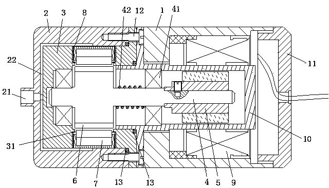
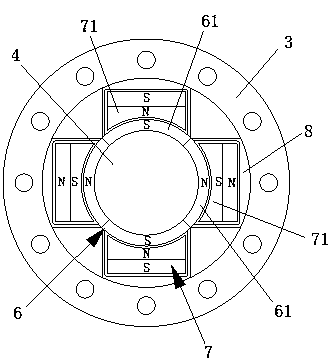
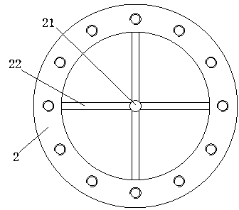
[0017] Such as Figure 1-Figure 3 A magnetic drive piston type valveless compressor shown includes a motor casing 1, the two ends of the motor casing 1 are respectively connected with a cylinder head 2 and a rear cover 11, the cylinder head 2 is provided with a cylinder liner 3, and the compressor also includes Crankshaft 4, one end of crankshaft 4 is coaxially provided with motor rotor 5 and this end is positioned at motor casing 1, and the other end of crankshaft 4 is coaxially provided with magnetic force rotor 6 and this end is positioned at cylinder liner 3, and also sets in cylinder liner 3 There is a magnetic piston 7 matched with the magnetic rotor 6, and the magnetic rotor 6 forms an adsorption or repulsion state with the magnetic piston 7 under the rotating force of the crankshaft 4, so that the magnetic piston 7 is in a state of continuous reciprocating motion, a...


PUM


Abstract

The invention relates to a magnetic transmission piston-type valveless compressor, which comprises a motor case. The two ends of the motor case are respectively connected with a cylinder head and a rear cover. A cylinder liner is arranged in the cylinder head. The compressor additionally comprises a crankshaft. A motor rotor is coaxially arranged at one end of the crankshaft. A magnetic rotor is coaxially arranged at the other end of the crankshaft. A magnetic piston which is matched with the magnetic rotor is additionally arranged in the cylinder liner. The magnetic rotor and the magnetic piston form an attraction or repulsion state under the rotating acting force of the crankshaft to enable the magnetic piston to be in a continuous reciprocating motion state. An exhaust passage which is communicated with the cylinder head and the magnetic piston is additionally arranged between the cylinder head and the magnetic piston. According to the technical scheme, by driving the magnetic piston to move circumferentially through the crankshaft and by using the principle of homopolar repulsion and heteropolar attraction, the continuous reciprocating motion of the magnetic piston in a cylinder is realized, the process of compressing air is completed and the compressed air is exhausted out of the compressor through the exhaust passage.

Description

technical field [0001] The invention relates to a compressor, in particular to a magnetic drive piston type valveless compressor. Background technique [0002] At present, the compressors used in the refrigeration and air-conditioning industry mainly include piston type, screw type, rotary type, centrifugal type and scroll type. Among them, the piston compressor is the earliest compressor designed, manufactured and applied. It is also the compressor with the widest application range and the most mature manufacturing process. It is the most widely used type in small and medium-sized commercial refrigeration systems. However, due to the design principle of the original structure of the piston compressor, there are still many problems and shortcomings: for example, there are too many moving parts, the structure is complicated, the maintenance workload is large, and the maintenance cost is high; the force is unbalanced, and there is no way to control the reciprocation Inertial ...

Claims


Application Information

Patent Timeline
Patent Type & Authority Applications(China)
IPC IPC(8): F04B35/00F04B39/12F04B39/00
Inventor 李冰何世安
Owner CHINA ELECTRONICS TECH GROUP CORP NO 16 INST
Why Eureka
Try Eureka