Pressure valve debugging system

A technology for debugging systems and pressure valves. It is used in fluid pressure actuation system testing, fluid pressure actuation devices, and mechanical equipment. It can solve problems affecting the cleanliness of the hydraulic system, inability to complete pressure adjustment, and insufficient wrench space. The effect of preventing the impact of cleanliness, reducing requirements, solving operating space constraints

Active Publication Date: 2016-06-08
ZOOMLION HEAVY IND CO LTD
View PDF5 Cites 0 Cited by
  • Summary
  • Abstract
  • Description
  • Claims
  • Application Information

AI Technical Summary

Problems solved by technology

However, as the functions of hydraulic systems such as cranes are becoming more and more perfect, the number of relief valves and pressure reducing valves that need to be adjusted is increasing, and the problem of continuing to use the method of adjusting the pressure of the pressure valve during the actual product debugging process has gradually become prominent.
[0004] First of all, in debugging products, different pressure valves are connected in different ways in different circuits, and the adjustment methods of each pressure valve are also different, so the operator is required to have a certain understanding of the principles of each pressure valve and the circuit it is connected to, otherwise Unable to complete pressure regulation
Secondly, in the commissioning of the product, limited by the installation position of the pressure valve, surrounding pipelines and other components, there is not enough space for the wrench, which is not easy to operate
Thirdly, some pressure valves can directly adjust the pressure through the corresponding action; some pressure valves need to modify the pipeline, and the disassembly and assembly of the pipeline will affect the cleanliness of the entire hydraulic system of the commissioning product

Method used


Image

  • Pressure valve debugging system
  • Pressure valve debugging system
  • Pressure valve debugging system

Examples


Embodiment Construction

[0022] The present invention will be described in detail below with reference to the accompanying drawings and examples.

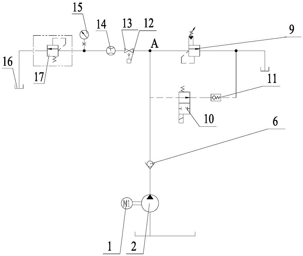
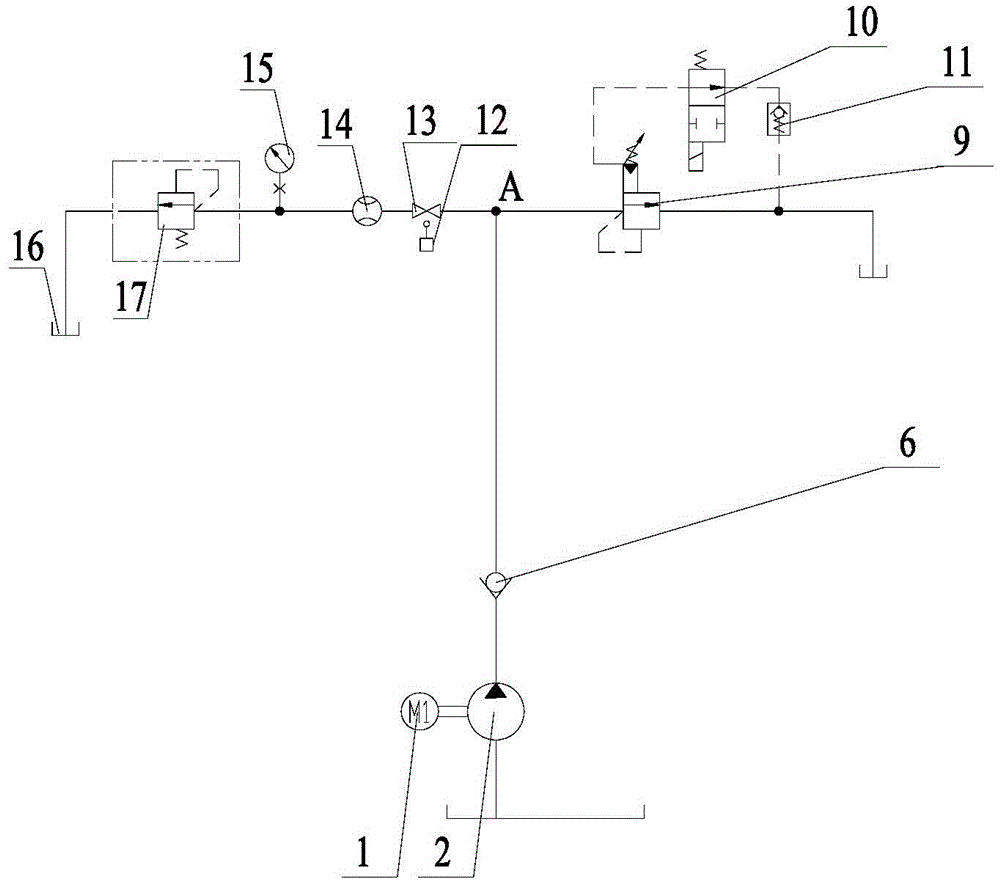
[0023] Such as figure 1 and figure 2 As shown, the pressure valve debugging system according to the present invention includes an oil supply circuit, a pressure regulating test oil circuit and a pressure limiting oil circuit, the oil supply circuit includes at least one oil pump, and the output pipeline of the oil pump has a first output node A; The test oil circuit is connected with the first output node A, and is used for installing the pressure valve 17 to be adjusted. The pressure regulation test oil circuit includes a flow meter 14 and a pressure detection connection arranged in series between the pressure valve 17 to be adjusted and the first output node A. The input point; the pressure limiting oil circuit is connected with the first output node A, and is used to limit the pressure of the pressure regulating test oil circuit. In the present inven...


PUM


Abstract

The invention provides a pressure valve debugging system, comprising: an oil supply circuit, including at least one oil pump, the output pipeline of the oil pump has a first output node; a pressure regulation test oil circuit, connected to the first output node, used for installation The pressure regulating valve, the pressure regulating test oil circuit includes a flow meter and a pressure detection access point arranged in series between the pressure valve to be regulated and the first output node; the pressure limiting oil circuit is connected to the first output node and is used to limit the Pressure test oil circuit pressure. In the present invention, the pressure valve to be adjusted is connected to the pressure regulating test oil circuit, and the oil supply circuit regulates the pressure and flow of the pressure regulating test oil circuit, that is, the pressure valve to be adjusted adopts a unified connection mode, and the pipeline does not need to be modified during adjustment, thereby Effectively reduce the operation volume of pressure adjustment, solve the problem of limited operating space, and prevent the impact of disassembly and assembly of pipelines on the cleanliness of the hydraulic system; in addition, pressure adjustment operators do not need to understand the working principle of the circuit, reducing the requirements of operators.

Description

technical field [0001] The invention relates to the field of pressure regulating test devices for pressure valves, in particular to a pressure valve debugging system. Background technique [0002] The functions of hydraulic systems such as large-tonnage cranes are becoming more and more perfect, and the flow and pressure of different circuits are different. Pressure valves such as relief valves and pressure reducing valves of different specifications are often used to limit pressure. Whether each overflow valve and pressure reducing valve can accurately adjust the pressure of each pressure valve according to the design has a great influence on the normal operation of the crane. In addition, the pressure drop of the pressure valve is different under different flow rates. In order to adjust the pressure valve accurately, an appropriate flow rate must be provided. [0003] Due to the relatively simple functions of earlier hydraulic systems such as cranes, there are relatively ...

Claims


Application Information

Patent Timeline
Patent Type & Authority Patents(China)
IPC IPC(8): F15B19/00
Inventor 苏光磊
Owner ZOOMLION HEAVY IND CO LTD
Why Eureka
Try Eureka