Pneumatic draining valve for locomotive air source system filter

A technology of filter and drain valve, which is applied in the direction of sliding valve, valve details, valve device, etc., can solve the problems of automatic drainage sticking, etc., and achieve the effect of ensuring work performance, eliminating sticking phenomenon, and eliminating long exhaust phenomenon

Inactive Publication Date: 2013-12-18
SHIJIAZHUANG JIAXIANG PRECISION MASCH CO LTD
View PDF8 Cites 9 Cited by
  • Summary
  • Abstract
  • Description
  • Claims
  • Application Information

AI Technical Summary

Problems solved by technology

[0004] The purpose of the present invention is to provide an air-operated drain valve for the filter of the locomotive air source system to solve the problem of the existing automatic drain due to the failure of the elastic element and the stagnation phenomenon

Method used


Image

  • Pneumatic draining valve for locomotive air source system filter
  • Pneumatic draining valve for locomotive air source system filter
  • Pneumatic draining valve for locomotive air source system filter

Examples


Embodiment Construction

[0018] The present invention will be further described below through specific embodiments.

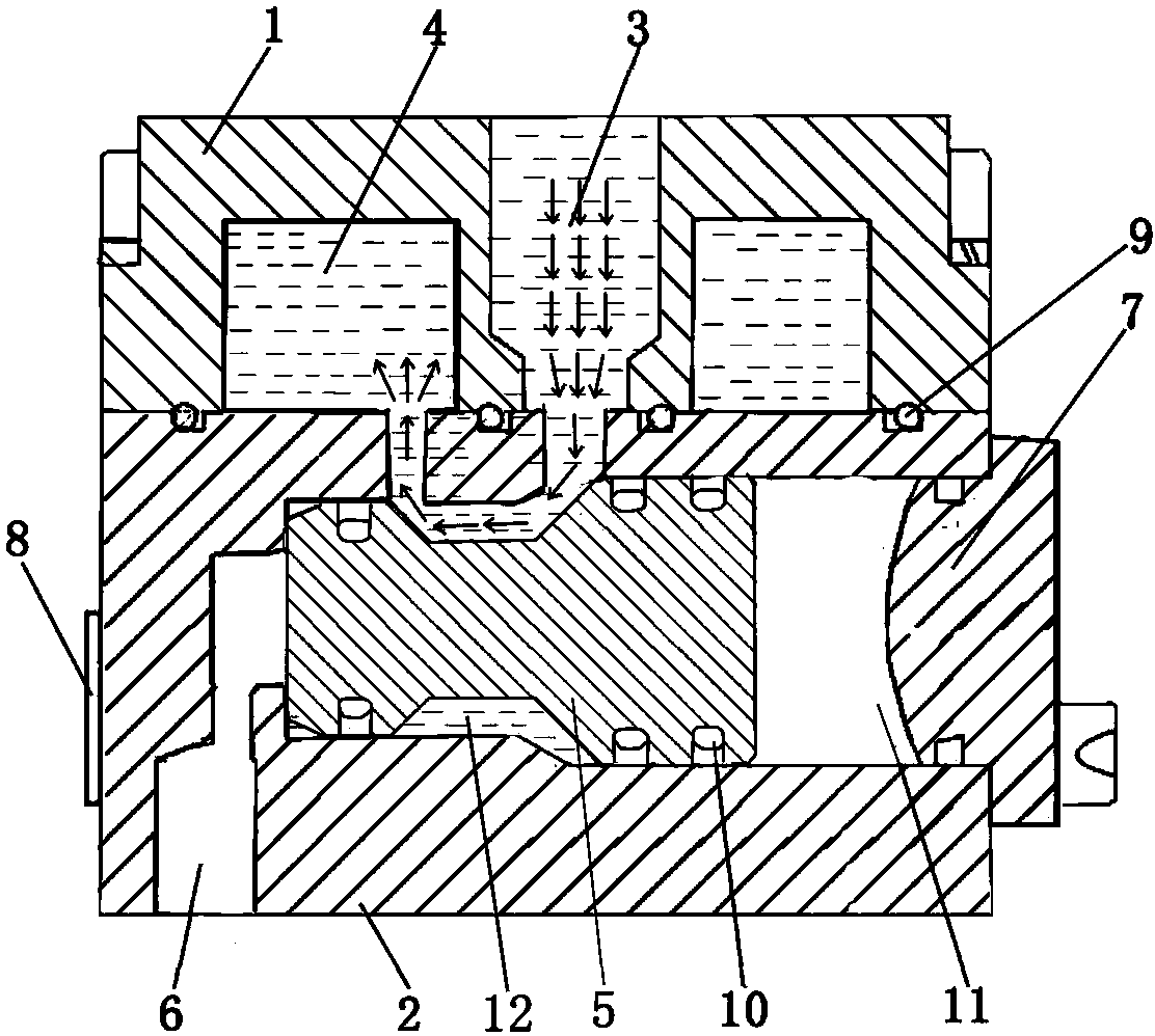
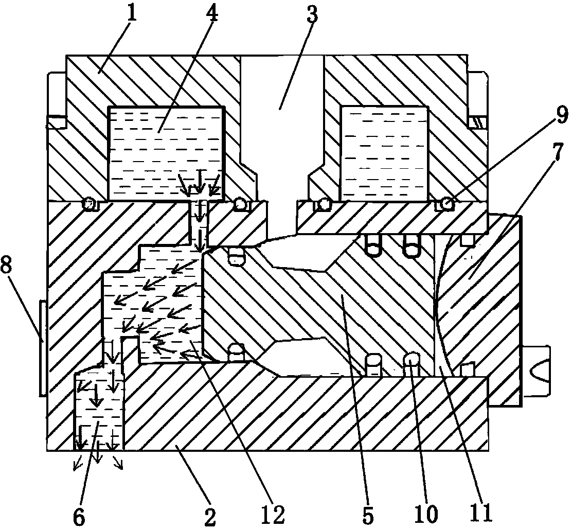
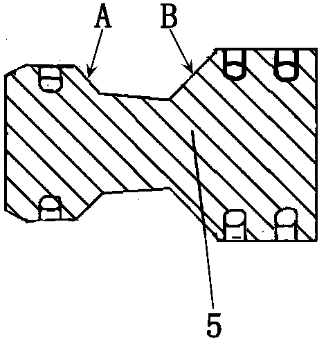
[0019] Such as figure 1 , figure 2 As shown, the main structure of the present invention is composed of an upper valve body 1 and a lower valve body 2 fixed by fastening screws and butted together, and an O-ring 9 is used between the upper valve body 1 and the lower valve body 2 Sealing; the upper valve body 1 is provided with a filter interface 3 and a dirt storage chamber 4, and the lower valve body 2 is provided with a sewage passage 6 and a piston chamber 12, and the filter interface 3, dirt storage chamber 4 and sewage passage 6 are all open In the piston cavity 12; the right end of the piston cavity 12 is closed by a closing cover 7 fixed on the lower valve body 2, and a dumbbell-shaped piston 5 is arranged in the piston cavity 12 ( image 3 As shown), a gas chamber 11 is formed between the piston 5 and the closing cover 7, and an external gas source (not shown in the figure) ...


PUM


Abstract

The invention discloses a pneumatic draining valve for a locomotive air source system filter. The pneumatic draining valve comprises a shell provided with a filter port, a sewage storage cavity, a draining passage and a piston cavity. A gas cavity which can be inflated and deflated is formed between a piston and the right end of the piston. The piston is of a dumbbell shape and includes a left piston part, a right piston part and a middle load bearing part. The middle load bearing part is provided with a left stress face and a right stress face. The area of the left stress face is smaller than that of the right stress face. By the pneumatic draining valve, long exhaust when an electromagnetic draining valve is used is eliminated. Due to the fact that no elastic components are used and only air pressure is used to push the valve element (namely the piston) to move, blocking, caused by elastic component failure, of the existing pneumatic draining valves is eliminated. The application environmental temperature range of the draining valve is widened by a heating rod. In addition, the pneumatic draining valve is simple in structure and low in cost, and use and maintenance cost are lowered.

Description

technical field [0001] The invention relates to an automatic drain valve for a rail transit locomotive, in particular to an air-controlled drain valve for a filter of an air source system of a locomotive. Background technique [0002] Air source systems on rail locomotives are generally equipped with compressed air filters, and drain valves are installed on the interfaces of the filters. Most of the existing filter blowdown valves are solenoid valves. However, in practical applications, solenoid valves are often limited by electrical parameters, environment and their own mechanisms, so the failure rate is relatively high. In order to solve the defects in the application of solenoid valves, some locomotives are currently using manual drain valves. Although manual drain valves avoid some disadvantages caused by the use of solenoid valves, manual drain valves can only be operated when parking. This not only increases the workload, but also virtually increases the cost of locom...

Claims


Application Information

Patent Timeline
Patent Type & Authority Applications(China)
IPC IPC(8): F16K3/22F16K3/30F16K31/122F16K49/00
Inventor 孙俊虎孙文朝
Owner SHIJIAZHUANG JIAXIANG PRECISION MASCH CO LTD
Why Eureka
Try Eureka