

Light source device and image display apparatus
A technology of a light source device and a light source unit, which is applied in the direction of lighting devices, projection devices, lighting device components, etc., can solve the problems of reduced durability of lenses and mirrors, low transmittance of optical resins, and reduced light utilization efficiency, etc., and achieves miniaturization The effect of the number of parts
- Summary
- Abstract
- Description
- Claims
- Application Information
AI Technical Summary
Problems solved by technology
Method used
Image

Examples
Embodiment 1
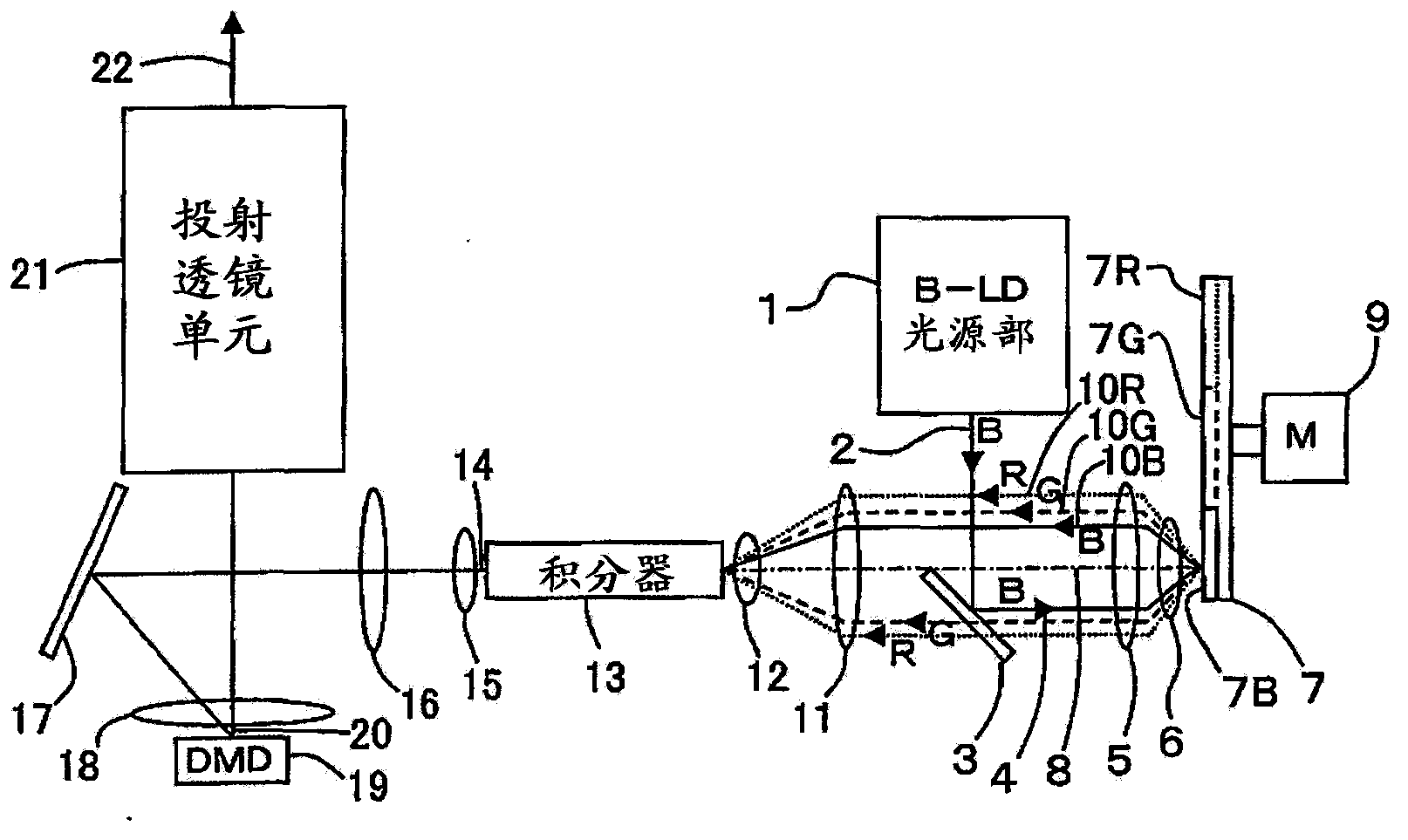
[0025] figure 1 It is a top view showing main parts of the light source device and the image display device according to the first embodiment of the present invention.
[0026] Blue (B) light 2 that becomes substantially parallel light from a blue laser diode (B-LD) light source unit 1 enters a dichroic mirror 3 . Hereinafter, the blue laser diode is abbreviated as B-LD, and the blue is abbreviated as B. The B-LD light source unit 1 is composed of a plurality of B-LDs not shown. The dichroic mirror 3 has spectral transmissive reflectance characteristics that reflect B light, transmit green (G) light, and transmit red (R) light. Hereinafter, green is abbreviated as G, and red is abbreviated as R.
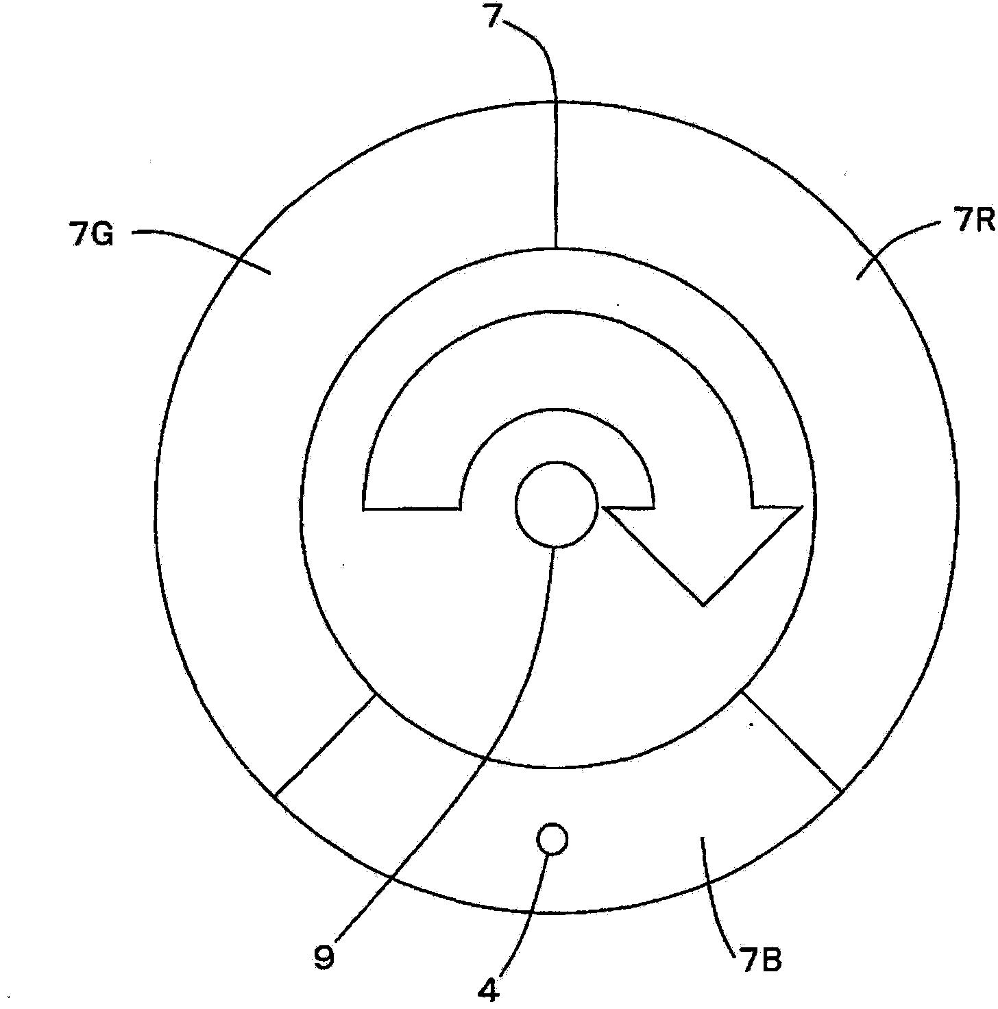
[0027] The B light 4 reflected by the dichroic mirror 3 is refracted by the lenses 5 and 6 , condensed to approximately one point, and enters the color wheel 7 .
[0028] The lens 5 and the lens 6 are configured to have a common optical axis 8 , and the B light 4 is deviated fro...
Embodiment 2
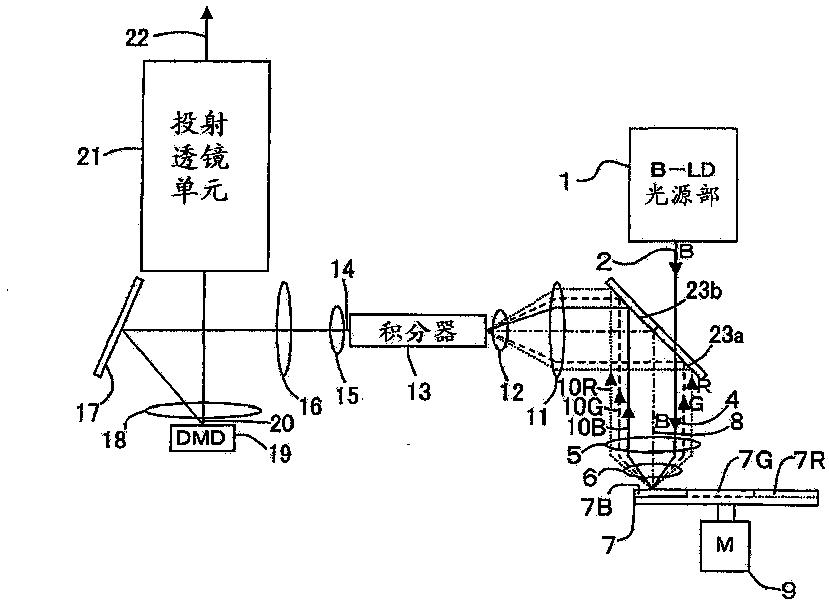
[0042] image 3 It is a top view showing main parts of a light source device and an image display device according to Embodiment 2 of the present invention. Here, the numbers in the accompanying drawings represent the same figure 1 , figure 2 same part.
[0043] The B light 2 from the B-LD light source unit 1 that becomes substantially parallel light enters the dichroic mirror 23 a. The dichroic mirror 23 a has spectral transmission reflectance characteristics of transmitting B light, reflecting G light, and reflecting R light.
[0044] The B light 4 transmitted through the dichroic mirror 23 a is refracted by the lenses 5 and 6 , condensed to approximately one point, and enters the color wheel 7 .
[0045] The lens 5 and the lens 6 are configured to have a common optical axis 8, and the B light 4 is deviated from the optical axis 8 by approximately half to the right in the drawing. That is, the dichroic mirror 23a is disposed approximately halfway to the right of the op...
Embodiment 4
[0079] Figure 6 It is a top view showing main parts of a light source device and an image display device according to Embodiment 4 of the present invention.
[0080] The B light 2 that is substantially parallel light from the B-LD light source unit 1 enters the dichroic mirror 31 a. The dichroic mirror 31 a has a spectral transmission reflectance characteristic of transmitting B light, reflecting G light, and transmitting R light.
[0081] The B light 4 transmitted through the dichroic mirror 31 a is refracted by the lenses 5 and 6 , is condensed to approximately one point, and enters the color wheel 25 .
[0082] The lens 5 and the lens 6 are configured to have a common optical axis 8, and the B light 4 is deviated from the optical axis 8 by approximately half to the right in the drawing. In other words, the dichroic mirror 31 a is disposed approximately halfway to the right of the optical axis 8 in the drawing.
[0083] Color Wheel 25 with Figure 5 Similar to the third...
PUM
 Abstract
Description
Claims
Application Information