Natural gas liquefying method and device with light hydrocarbon recovery function

A light hydrocarbon recovery and natural gas technology, applied in liquefaction, refrigeration, liquefaction, solidification, etc., can solve the problems of low separation precision of light hydrocarbons, low LNG recovery rate, and low quality of condensate, and achieve rich product specifications and simple equipment configuration , The effect of simple and cheap operation

Inactive Publication Date: 2013-12-18
HANGZHOU FORTUNE CRYOGENIC EQUIP CO LTD
View PDF6 Cites 19 Cited by
  • Summary
  • Abstract
  • Description
  • Claims
  • Application Information

AI Technical Summary

Problems solved by technology

[0004] The present invention aims at the disadvantages of the prior art that the separation precision of light hydrocarbons is low, resulting in low LNG recovery rate, low light hydrocarbon recovery rate, and the quality of the separated condensate is not high, which cannot meet the relevant national standards, and provides a recyclable and Natural gas liquefaction method and device for obtaining high-purity light hydrocarbons

Method used


Image

  • Natural gas liquefying method and device with light hydrocarbon recovery function
  • Natural gas liquefying method and device with light hydrocarbon recovery function

Examples


Embodiment 1

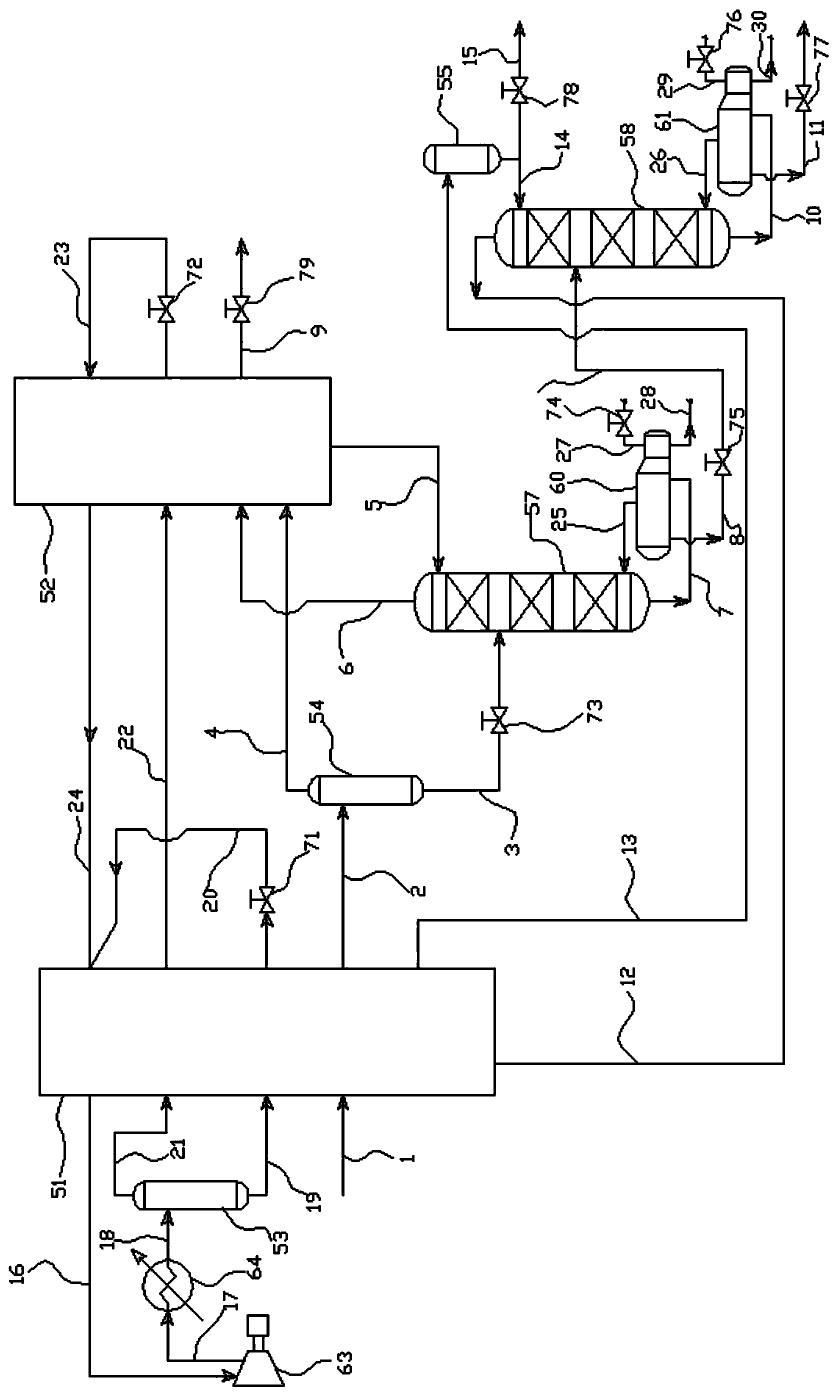
[0046] A natural gas liquefaction method and device thereof with light hydrocarbon recovery, such as figure 1 As shown, it includes a natural gas liquefaction plant with light hydrocarbon recovery. The natural gas liquefaction plant with light hydrocarbon recovery includes a first separator 53, a second separator 54, a refrigerant compressor 63, and a compressor aftercooler 64. Heaters, rectification towers, storage tanks numbered Ⅰ~Ⅴ, control valves numbered a~i and pipelines numbered a~k, m~z and aa~ae, wherein the heat exchanger includes the first heat exchange 51 and the second heat exchanger 52, the rectification column includes the first rectification column 57 with the first bottom reboiler 60, the second bottom reboiler 61 with the first column top separator 55 Second distillation tower 58. In this embodiment, the control valve a71, the control valve b72 and the control valve i79 are all J-T valves.

[0047] The pipeline a1 is connected with the first heat exchanger ...

Embodiment 2

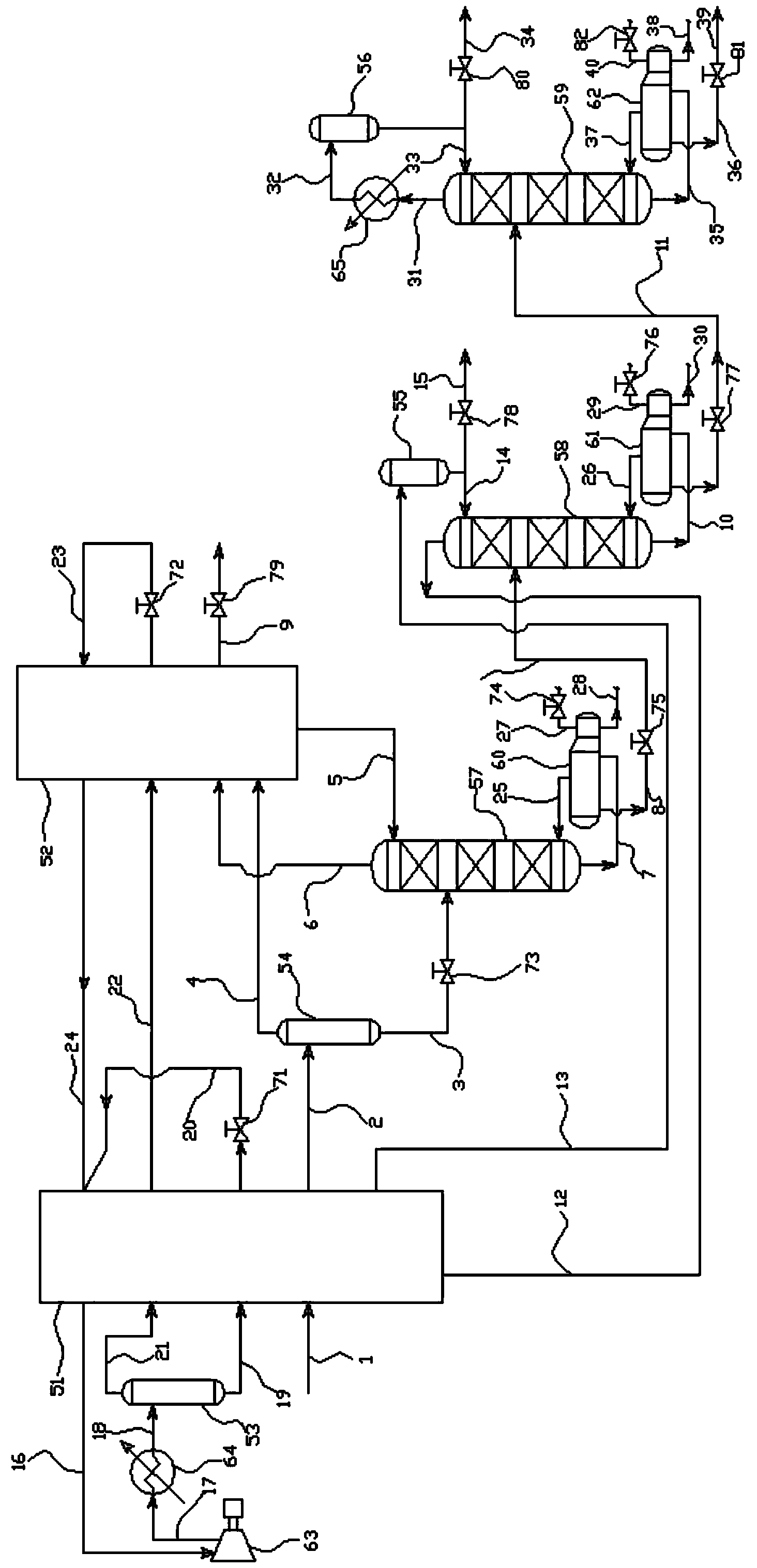
[0077] A natural gas liquefaction method and device thereof with light hydrocarbon recovery, such as figure 2 As shown, it includes a natural gas liquefaction plant with light hydrocarbon recovery. The natural gas liquefaction plant with light hydrocarbon recovery includes a first separator 53, a second separator 54, a refrigerant compressor 63, and a post-compressor separator 64. Heaters, rectification towers, storage tanks numbered Ⅰ~Ⅴ, control valves numbered a~k and m, pipelines numbered a~k, m~z, aa~ak and am~ao, in which heat exchange The device includes a first heat exchanger 51 and a second heat exchanger 52, and the rectification column includes a first rectification column 57 with a first bottom reboiler 60, and a second bottom reboiler 61 with a first column A second rectification column 58 with an overhead separator 55, and a third rectification column 59 with a third bottom reboiler, an overhead condenser 65 and a second overhead separator 56. In this embodiment...


PUM


Abstract

The invention relates to techniques of recovery of light hydrocarbon through separation of natural gas, and discloses a natural gas liquefying method and device with a light hydrocarbon recovery function. The natural gas liquefying method comprises the steps of pre-cooling, separating light hydrocarbon, liquefying natural gas, recovering the light hydrocarbon and the like, wherein C2<+> in feed gas is respectively extracted and separated into qualified products by a rectification and separation method, and a refrigeration technical process is circulated by utilizing a mixed refrigerant, so that the liquefication of the natural gas and the recovery of the light hydrocarbon can be realized in the same device. According to the natural gas liquefying method and device with the light hydrocarbon recovery function, which are disclosed by the invention, by aiming at an air source with larger moisture proportion in a natural gas liquefying device, the C2<+> light hydrocarbon is recovered while LNG (liquefied natural gas) is obtained through the liquefication, so that the quality of the LNG can regulated, the influence of C3<+> component left in the LNG on the safety operation of a device in a deep cooling section is reduced, and cheap and high-purity chemical materials can be obtained.

Description

technical field [0001] The invention relates to a technology for separating and recovering light hydrocarbons from natural gas, in particular to a natural gas liquefaction method with recovery of light hydrocarbons and a device thereof. Background technique [0002] With the continuous enrichment of domestic natural gas sources, the moisture in the feed gas in the liquefaction unit (C 2 + ) ratio has a large range of fluctuations, and where C 2 + It is an important chemical raw material and can produce high value-added chemical products. If it is separated and recycled, there will be significant social and economic benefits. [0003] At present, there are many devices and methods for recovering light hydrocarbons from natural gas pipeline gas in China. These devices and methods only separate and recover light hydrocarbons in pipeline natural gas, and the separated methane gas is still returned to the pipeline network. liquefaction. In domestic liquefied natural gas devi...

Claims


Application Information

Patent Timeline
Patent Type & Authority Applications(China)
IPC IPC(8): F25J3/02
CPCF25J1/0022F25J1/0055F25J1/0212F25J1/0237F25J1/0238F25J3/0209F25J3/0233F25J3/0238F25J3/0242F25J3/0247F25J2200/02F25J2200/70F25J2200/74F25J2205/04F25J2215/04F25J2215/62F25J2215/64F25J2260/02F25J2260/20F25J2270/18F25J2270/66
Inventor 杨雪婷杜宏鹏陶利民黄荣乜雯雯梁建国何伟颖
Owner HANGZHOU FORTUNE CRYOGENIC EQUIP CO LTD
Why Eureka
Try Eureka