Method and device for monitoring slope deformation and damage based on optical time domain reflectometer technology

An optical time domain reflection and slope technology, applied in the field of slope geotechnical engineering, can solve problems such as difficult to accurately evaluate key slope disease sections, waste of monitoring engineering investment, and different engineering properties, to achieve intuitive and reliable real-time remote monitoring , easy real-time remote monitoring, low cost effect

Inactive Publication Date: 2013-12-18
中铁西北科学研究院有限公司深圳南方分院
View PDF6 Cites 8 Cited by
  • Summary
  • Abstract
  • Description
  • Claims
  • Application Information

AI Technical Summary

Problems solved by technology

[0004] (1) Due to the large number of slope projects, which are distributed in a scattered point and belt, the nature of the projects is different, and the stability states are different. It is difficult to accurately evaluate the key slopes or potential landslide disease sections, and the investment in monitoring projects is often wasted due to misjudgments and poor stability. Or due to the omission of potential landslides, hidden dangers of disease are buried, and there are often key monitoring and prevention, but no signs of deformation and damage are found. In more cases, slope deformation and damage often occur without any monitoring measures

Method used


Image

  • Method and device for monitoring slope deformation and damage based on optical time domain reflectometer technology
  • Method and device for monitoring slope deformation and damage based on optical time domain reflectometer technology
  • Method and device for monitoring slope deformation and damage based on optical time domain reflectometer technology

Examples


Embodiment Construction

[0022] In order to further illustrate the principle and structure of the present invention, preferred embodiments of the present invention will now be described in detail with reference to the accompanying drawings.

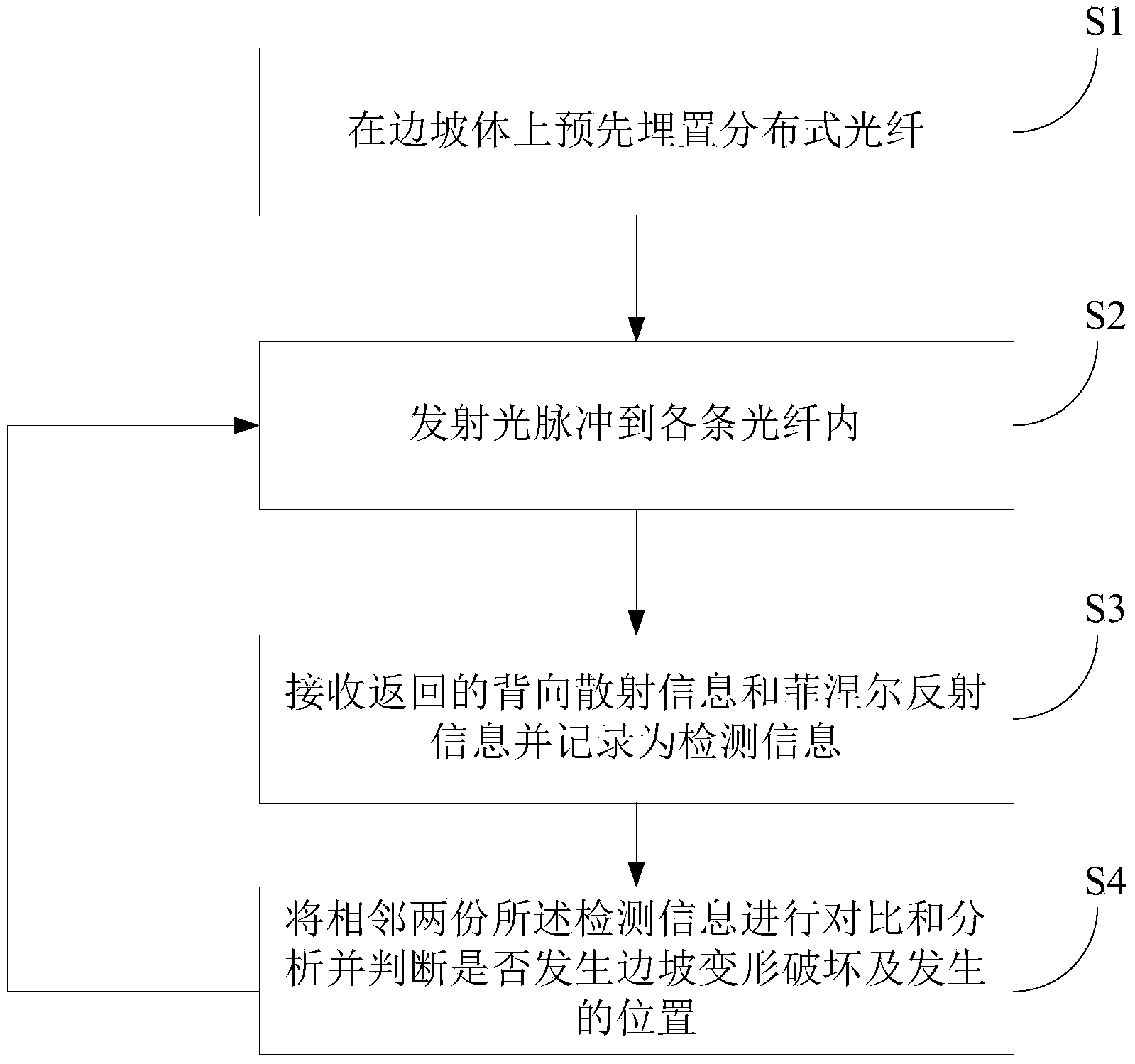
[0023] see figure 1 , the present invention provides a method for monitoring slope deformation and damage based on optical time domain reflectometry, the method comprising:

[0024] Step S1: Pre-embed distributed optical fibers on the slope body;

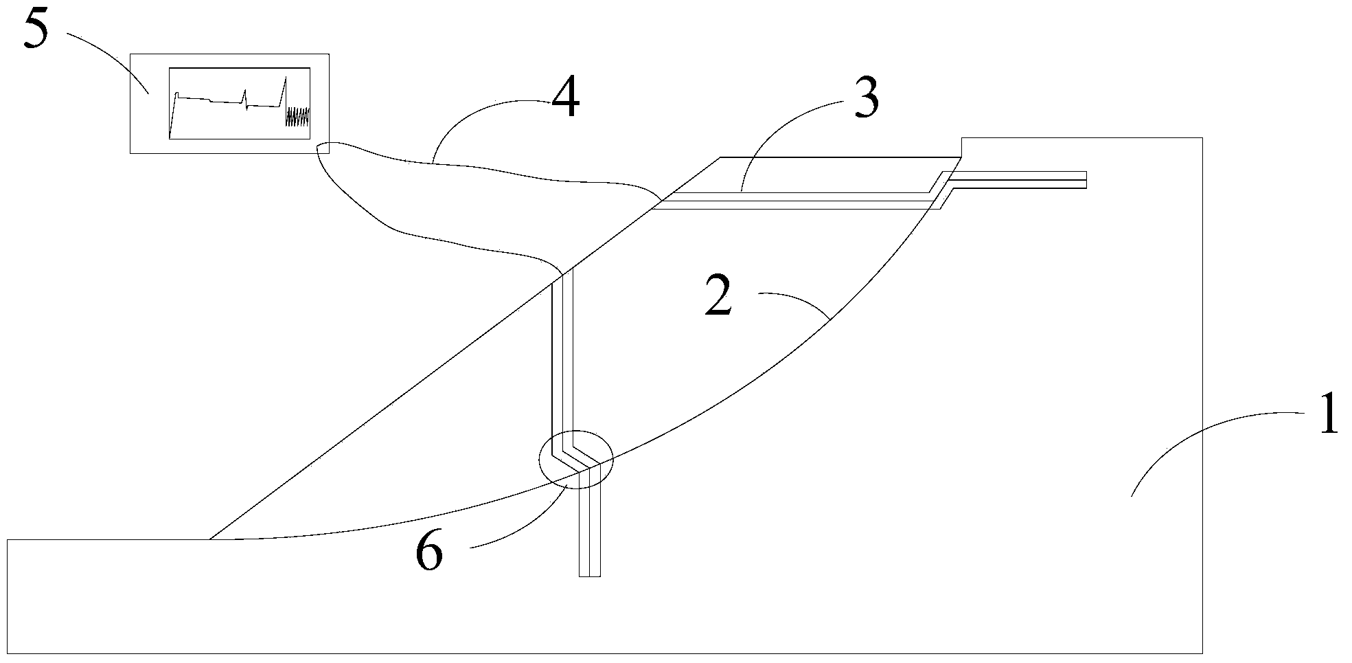
[0025] Such as image 3 As shown, the way of inserting the optical fiber into the slope can be various, for example, it can be divided into the direction of inserting into the slope 1 from the horizontal direction or inserting into the slope from the vertical direction and so on. Specifically, the optical fiber can be inserted into the slope 1 in various ways, for example, multiple optical fibers are excavated and buried in the shallow surface layer of the slope rock and soil, and multiple optical fibers are buried d...


PUM


Abstract

The invention relates to a method and device for monitoring slope deformation and damage based on the optical time domain reflectometer technology. The method for monitoring slope deformation and damage based on the optical time domain reflectometer technology includes the following steps that firstly, distributed optical fibers are pre-buried in a slope body; secondly, optical pulses are transmitted into all the optical fibers; thirdly, returned backscattering information and Fresnel reflection information are received and recorded as detection information; fourthly, two adjacent pieces of detection information are compared and analyzed to judge whether deformation and damage happen to a slope and the position of the deformation and the damage. The second step, the third step and the fourth step are repeated at set time intervals. According to the method for monitoring slope deformation and damage based on the optical time domain reflectometer technology, the position of macrobend deformation or breakage of the optical fibers is determined, thus, the deformation and the damage of a slope rock and earth mass is positioned through the position of macrobend deformation or breakage of the optical fibers.

Description

technical field [0001] The invention relates to slope geotechnical engineering, in particular to a method and device for monitoring slope deformation and damage based on optical time domain reflection technology. Background technique [0002] At present, during the construction and operation of slope projects, except for a few key high slope or landslide disease projects that have implemented key instrument monitoring, most slope projects have not deployed corresponding safety equipment in their design, construction and operation management. monitor. There are problems such as imperfect slope safety monitoring system, backward traditional observation methods, and serious lag in information analysis, which lead to maintenance and management personnel not being able to grasp the actual operation status of the slope project in a timely and accurate manner, and cannot provide scientific information for the effective management of the slope project. It not only directly affects ...

Claims


Application Information

Patent Timeline
Patent Type & Authority Applications(China)
IPC IPC(8): G01B11/16G01N21/84
Inventor 廖小平王建松赵杰林灿阳
Owner 中铁西北科学研究院有限公司深圳南方分院
Why Eureka
Try Eureka