Battery module

A battery module and battery technology, which is applied to battery components, circuits, electrical components, etc., can solve the problems that the battery cannot be connected to the conductive sheet, affects the discharge efficiency of the battery, and has a large resistance between the battery and the conductive sheet.

Inactive Publication Date: 2013-12-18
原瑞电池科技(深圳)有限公司 +1
View PDF4 Cites 1 Cited by
  • Summary
  • Abstract
  • Description
  • Claims
  • Application Information

AI Technical Summary

Problems solved by technology

[0003] In the above connection method, due to soldering, the resistance between the battery and the conductive sheet is relatively large, which affects the efficiency of battery discharge.
In addition, the solder is easy to fall off and cause false welding, so that the battery cannot be connected to the conductive sheet

Method used


Image

  • Battery module
  • Battery module
  • Battery module

Examples


Embodiment Construction

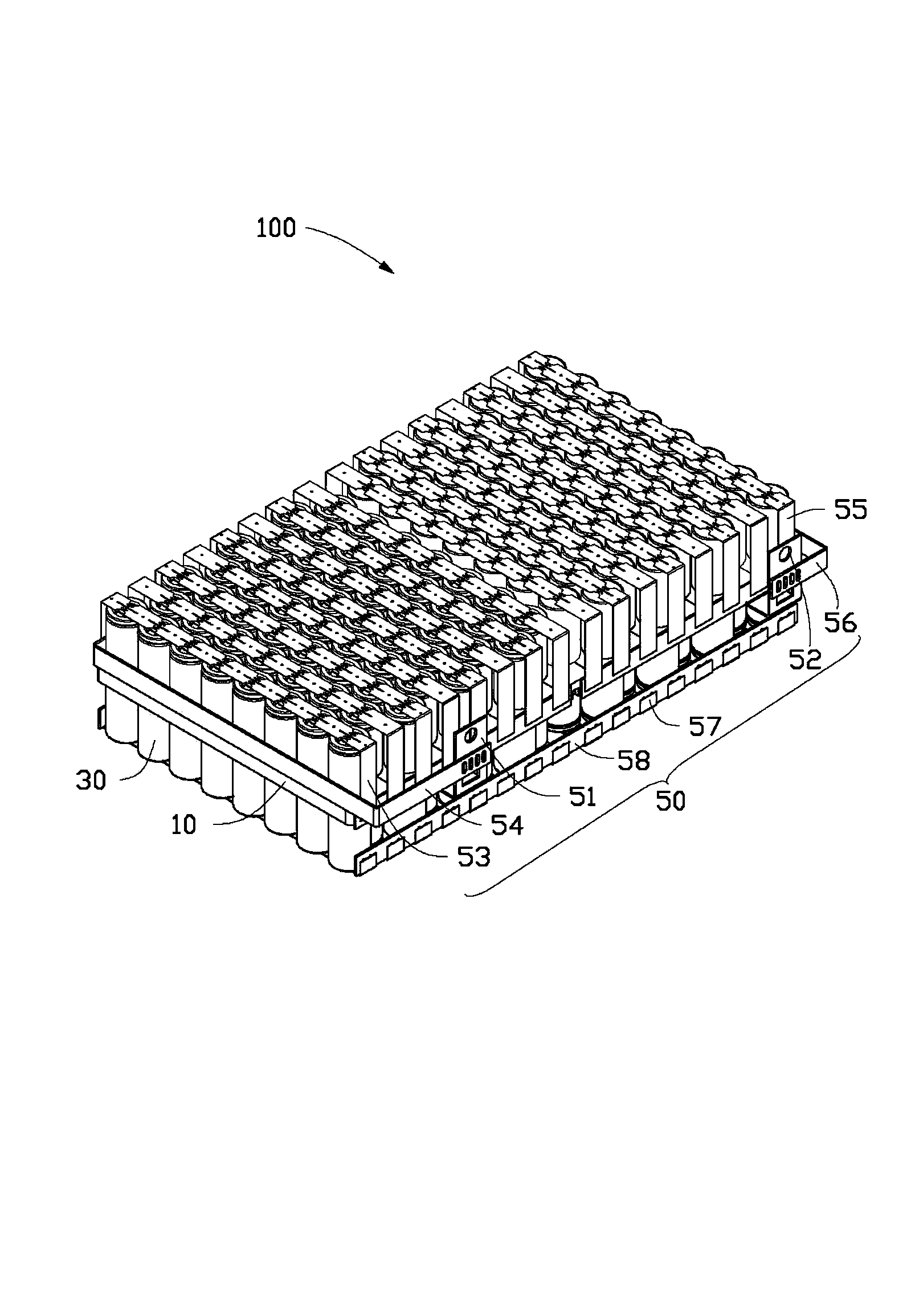
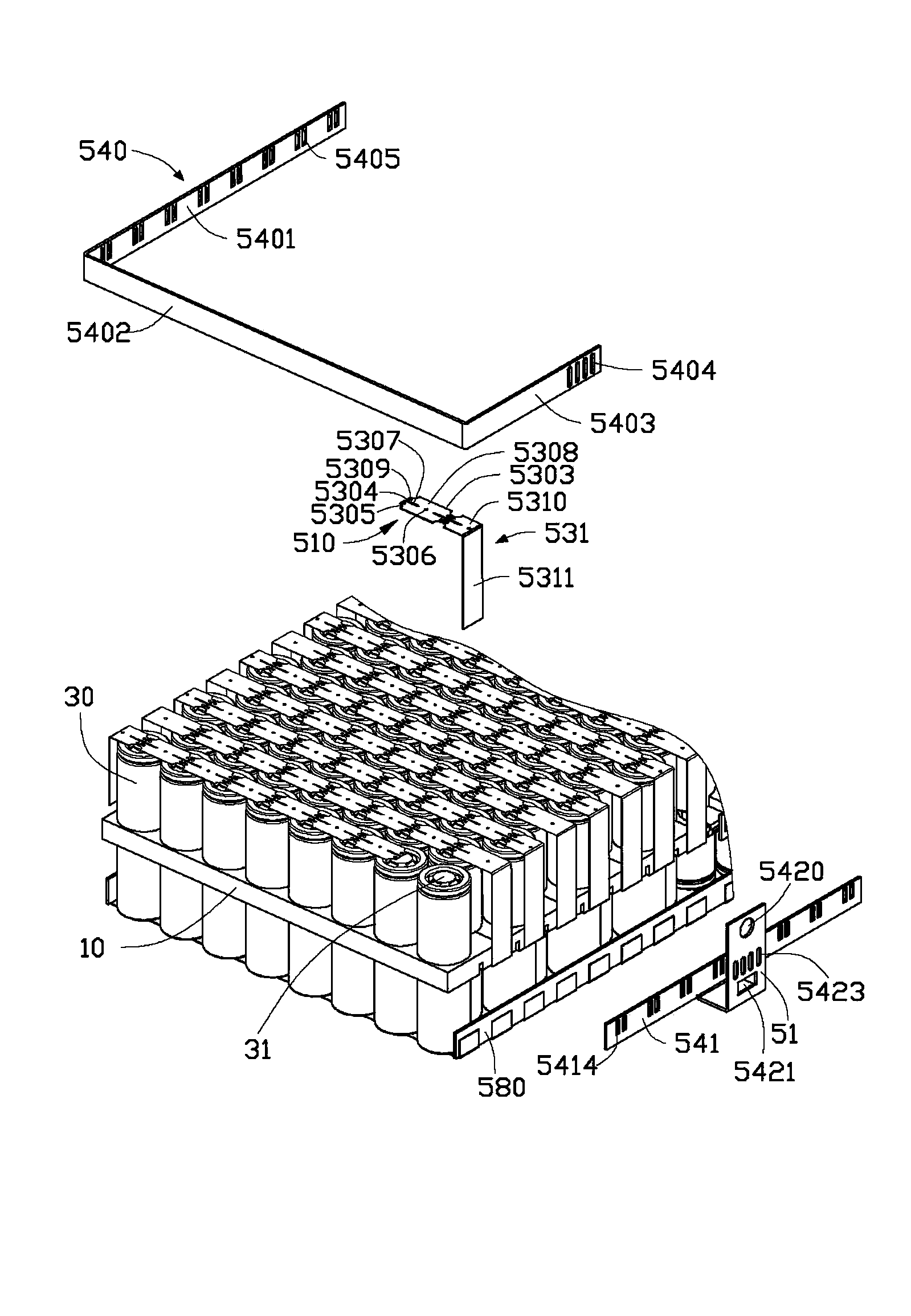
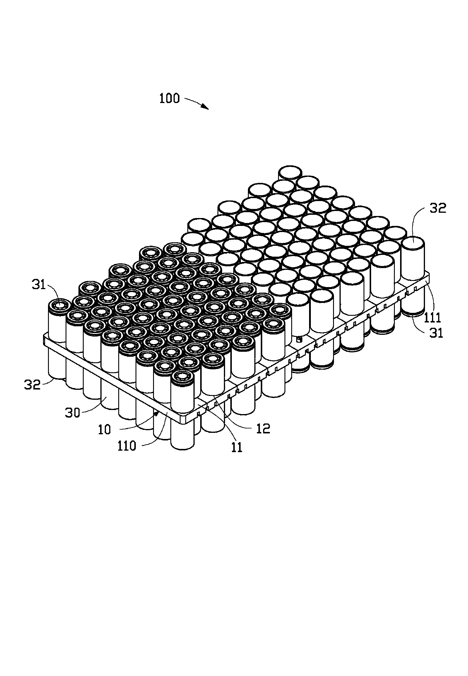
[0013] Please refer to Figure 1 to Figure 3 , the battery module 100 according to one embodiment of the present invention includes a battery holder 10 , a plurality of batteries 30 passing through the battery holder 10 , and a connection unit 50 connecting the batteries 30 together.

[0014] The battery holder 10 includes an upper surface 11 including a first end 110 and a second end 111 . The battery holder 10 also defines a plurality of rows of battery receiving holes 12 penetrating through the upper surface 11 . In this embodiment, 16 rows of battery receiving holes 12 are opened on the battery holder 10 , and are arranged at intervals of 8 or 7 in each row. Since the number of battery receiving holes 12 in two adjacent rows is different and arranged in a dislocation, the battery receiving holes 12 between different rows can be arranged more closely to save the area of ​​the entire battery holder 10 . The battery receiving holes 12 near the first end 110 and the battery ...


PUM


Abstract

The invention relates to a battery module, which includes a battery bracket, a plurality of batteries, and a connecting unit. The battery bracket is provided with multiple rows of battery accommodating holes. The plurality of batteries are disposed in the multiple rows of battery accommodating holes respectively. The connecting unit includes electrode sheets, a main confluence sheet group, and a plurality of sub-confluence sheet groups. Each sub-confluence sheet group is in parallel connection with a row of batteries, and comprises multiple first confluence sheets. Recesses for welding are formed on two ends of each first confluence sheet by stamping, and are respectively connected to one of two neighboring batteries by spot welding. The main confluence sheet group is connected to the electrode sheets, and is connected to both ends of each sub-confluence sheet group respectively.

Description

technical field [0001] The invention relates to the field of batteries, in particular to a battery module. Background technique [0002] Battery modules, such as lithium battery modules, generally use multiple batteries in parallel and in series to provide sufficient power. The number of these batteries will reach as many as dozens, and they will be fixed together by battery brackets. Multiple batteries will be connected to the positive or negative poles of the entire battery pack through conductive sheets. Wherein, the connection method between the conductive sheet and the battery is generally soldering. [0003] In the above connection method, the resistance between the battery and the conductive sheet is relatively large due to soldering, thereby affecting the discharge efficiency of the battery. In addition, the solder is easy to fall off and cause false welding, so that the battery cannot be connected to the conductive sheet. Contents of the invention [0004] In v...

Claims


Application Information

Patent Timeline
Patent Type & Authority Applications(China)
IPC IPC(8): H01M2/20H01M2/26H01M50/503H01M50/505H01M50/507H01M50/516
CPCY02E60/10
Inventor 孙瑞堂庄宗宪李仁智
Owner 原瑞电池科技(深圳)有限公司
Why Eureka
Try Eureka