Artificial lung and extracorporeal circulation device

A technology of extracorporeal circulation device and artificial lung, which is applied in the field of artificial lung and extracorporeal circulation device, and can solve problems such as inability to exert blood circulation.

Active Publication Date: 2013-12-18
TERUMO KK
View PDF6 Cites 8 Cited by
  • Summary
  • Abstract
  • Description
  • Claims
  • Application Information

AI Technical Summary

Problems solved by technology

If both the blood storage tank and the air bubble removal device are omitted, the air bubbles in the blood will flow into the cen

Method used


Image

  • Artificial lung and extracorporeal circulation device
  • Artificial lung and extracorporeal circulation device
  • Artificial lung and extracorporeal circulation device

Examples


Embodiment approach

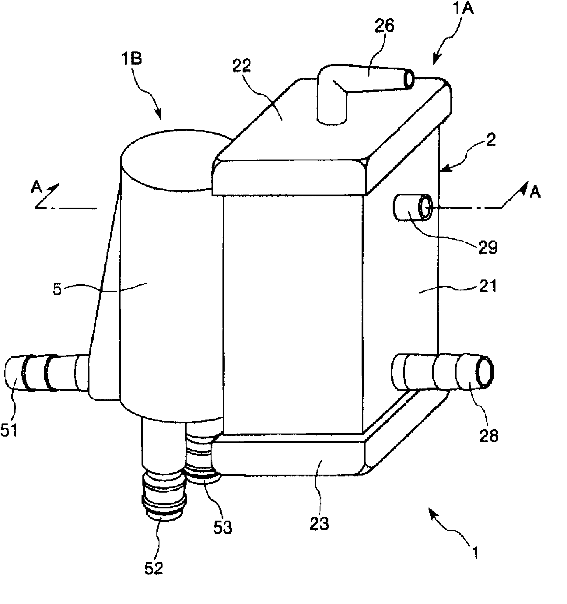
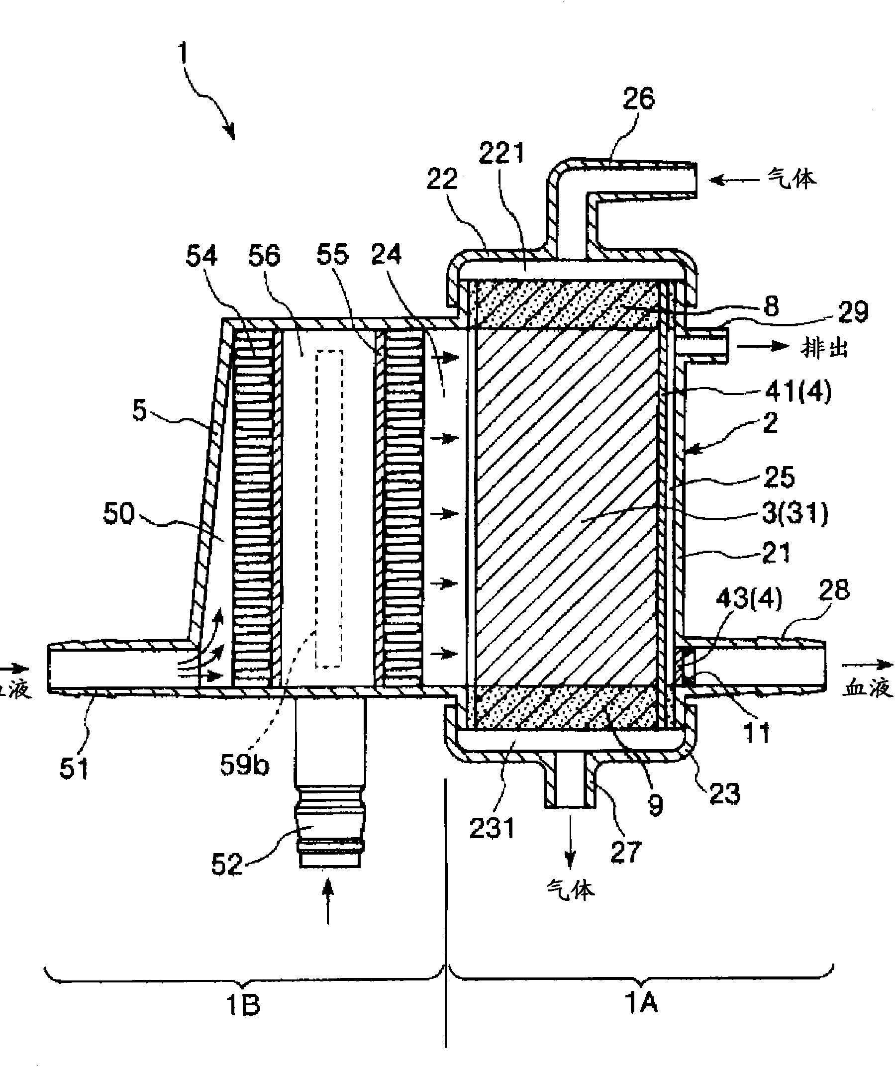
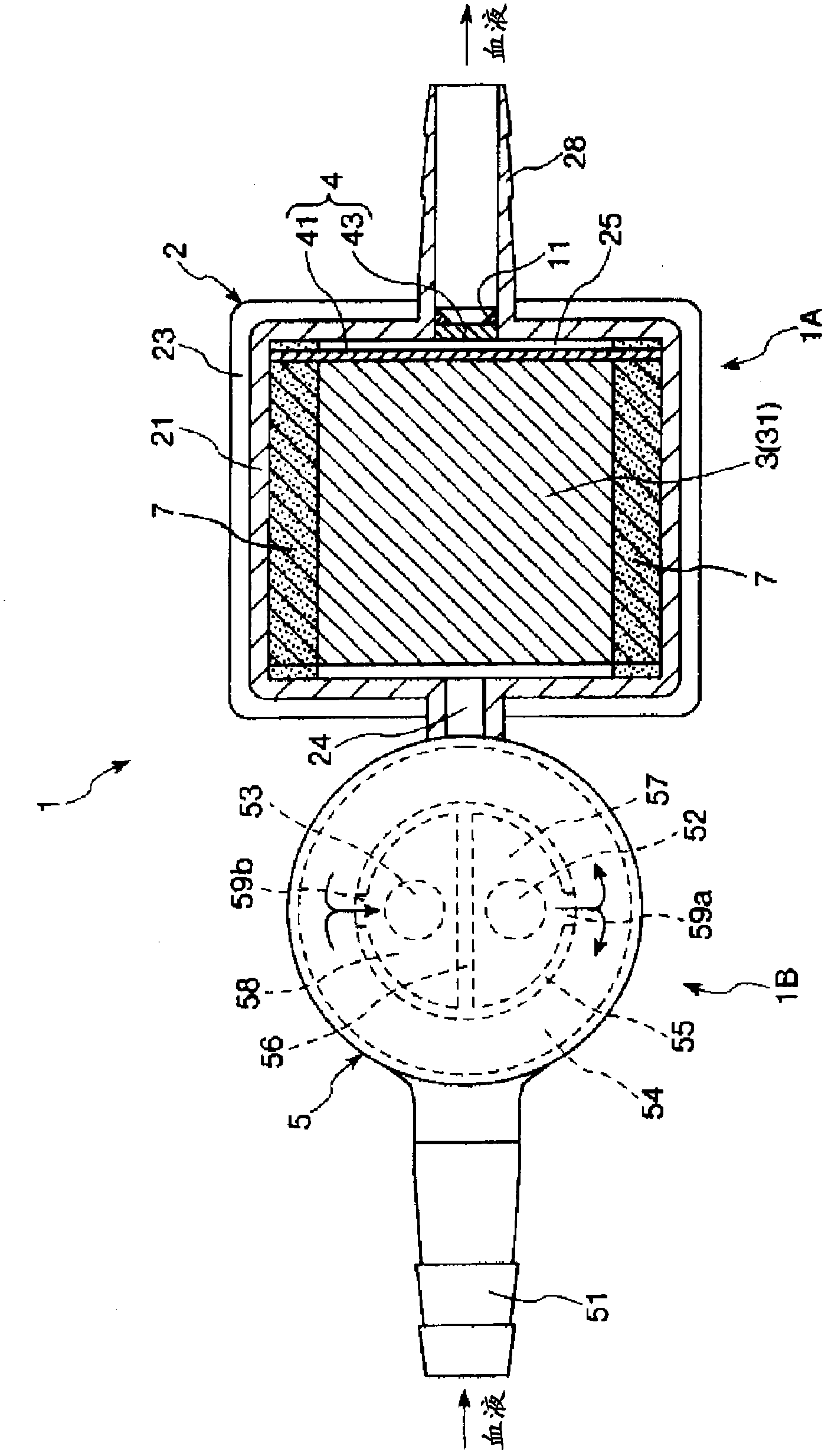
[0064] figure 1 It is a perspective view showing the first embodiment of the artificial lung of the present invention, figure 2 for figure 1 A-A line sectional view in, image 3 for figure 1 A cross-sectional view of the artificial lung in the shown artificial lung, Figure 4 for figure 2 The enlarged cross-sectional view of the lower right part (hollow fiber membrane layer, first filter member, and second filter member) in . It should be noted that the figure 1 and figure 2 The upper side is referred to as "upper" or "upper", the lower side is referred to as "lower" or "below", the left side is referred to as "blood inflow side" or "upstream side", and the right side is referred to as "blood outflow side" or "downstream side". "Be explained.

[0065] The artificial lung 1 of the illustrated embodiment is an artificial lung with a heat exchanger, for example, installed in an extracorporeal blood circulation circuit, and the artificial lung with a heat exchanger has ...

no. 2 Embodiment approach

[0136] Figure 5 It is a plan view showing a second embodiment of the artificial lung of the present invention, Figure 6 For viewing from the arrow B side Figure 5 The diagram of the artificial lung shown, Figure 7 for Figure 6 The C-C line sectional view in, Figure 8 for from Figure 6 In the diagram observed on the arrow D side, Figure 9 for Figure 5 E-E line sectional view in, Figure 10 for Figure 9 The F-F line sectional view in . It should be noted that the Figure 5 , Figure 7 and Figure 8 The left side in is called "left" or "left", and the right side is called "right" or "right". in addition, Figure 5 to Figure 10 In the description, the inner side of the artificial lung is referred to as the "blood inflow side" or "upstream side", and the outer side is referred to as the "blood outflow side" or "downstream side".


PUM

PropertyMeasurementUnit
The inside diameter ofaaaaaaaaaa
Wall thicknessaaaaaaaaaa
Pore diameteraaaaaaaaaa

Abstract

This artificial lung includes: a housing; a hollow fiber membrane layer that is housed inside the housing and in which a multitude of hollow fiber membranes having a gas exchange function are integrated; a gas inflow section and a gas outflow section that employ the lumen of each hollow fiber membrane as a gas flow path and that are provided respectively on the upstream side and the downstream side of the gas flow paths; a blood inflow section and a blood outflow section that employ the outside of the hollow fiber membranes as a blood flow path and that are provided respectively on the upstream side and the downstream side of the blood flow path; a first filter member that is provided in contact with the surface of the hollow fiber membrane layer on the side of the blood outflow section and covers almost the entire surface, the first filter member having the function of capturing bubbles in the blood; and a second filter member spaced away from the first filter member and arranged between the first filter member and the blood outflow section, the second filter member having the function of capturing bubbles in the blood.

Description

technical field [0001] The present invention relates to artificial lung (oxygenator) and extracorporeal circulation device. Background technique [0002] At present, as an extracorporeal circulation device used in cardiac surgery, the following extracorporeal circulation device is known: a bubble trap, a centrifugal pump, and an artificial lung are arranged sequentially from the upstream side of the flow path of the blood circulation, and they are connected to each other. Connect with a tube (for example, refer to Patent Document 1). In the extracorporeal circulation apparatus described in the aforementioned Patent Document 1, the air bubble removing device is a device for removing air bubbles from blood taken from a patient. In addition, a centrifugal pump is a blood pump that circulates blood so as to take blood from a patient and return the taken blood to the patient again. The artificial lung is a device having a hollow fiber membrane layer in which a plurality of holl...

Claims


Application Information

Patent Timeline
IPC IPC(8): A61M1/36A61M1/16
CPCA61M1/3666A61M1/3667A61M1/1698A61M1/3623
Inventor 竹内和彦
Owner TERUMO KK
Why Eureka
Try Eureka