Apparatus and method for monitoring a vascular access of a patient subjected to an extracorporeal blood treatment

a technology for extracorporeal blood treatment and apparatus, which is applied in the direction of other blood circulation devices, filtration separation, separation processes, etc., can solve the problems of reducing monitoring the efficiency of vascular access, and undesirable phenomenon of recirculation of blood

Inactive Publication Date: 2007-02-06
GAMBRO LUNDIA AB
View PDF128 Cites 56 Cited by
  • Summary
  • Abstract
  • Description
  • Claims
  • Application Information

AI Technical Summary

Benefits of technology

[0047]An advantage of the invention is that it provides indicative values of the efficiency of the vascular access simply, automatically, using devices (such as for example pressure transducers, blood pump, drainage pump) which are normally already present in machines for extracorporeal blood treatment. A further advantage is that the invention enables monitoring of the vascular access at any time during the extracorporeal blood treatment.
[0048]A further advantage of the invention is that the monitoring procedure does not cause extra stress to the patient. The procedure can be carried out by means of variations in the blood pump or the drainage pump flow rates, or both, within flow rate intervals which are normally compatible with the extracorporeal treatment the patient undergoes. The intervals can be those normally used during the course of therapy.
[0049]These aims and others besides are all attained by the invention as it is characterised in one or more of the appended claims.
[0050]In a special function of the invention, a mathematical model is used which contains at least two parameters in which a first parameter relates to the hemodynamics of the vascular access, and a second parameter relates to the blood flow rate in the extracorporeal circuit.
[0051]The mathematical model comprises a third parameter relating to at least one blood characteristic: this characterist

Problems solved by technology

One of the problems of extracorporeal blood treatment is monitoring the efficiency of the vascular access.
A reduced-efficiency vascular access can lead to the undesirable phenomenon of recirculation of blood during treatment.
Flow recirculation therefore consists in return (in the extracorporeal circuit) of blood which has already been subjected to treatment, with a consequent diminution in treatment efficiency.
This method has the drawback that it is necessary to intervene mechanically on the fistula to interrupt blood flow.
The use of a sensor to directly measure the blood flow rate in the fistula tract comprised between the withdrawal needle and the return needle leads to a certain constructional complication, as well as some discomfort for the patient.
The data deductible from the method described in EP 1 020 199 A2 is however limited: in particular, the method provides only a general indication of the hemodynamic state of the fistula, signalling the prese

Method used


Image

  • Apparatus and method for monitoring a vascular access of a patient subjected to an extracorporeal blood treatment
  • Apparatus and method for monitoring a vascular access of a patient subjected to an extracorporeal blood treatment
  • Apparatus and method for monitoring a vascular access of a patient subjected to an extracorporeal blood treatment

Examples


first example

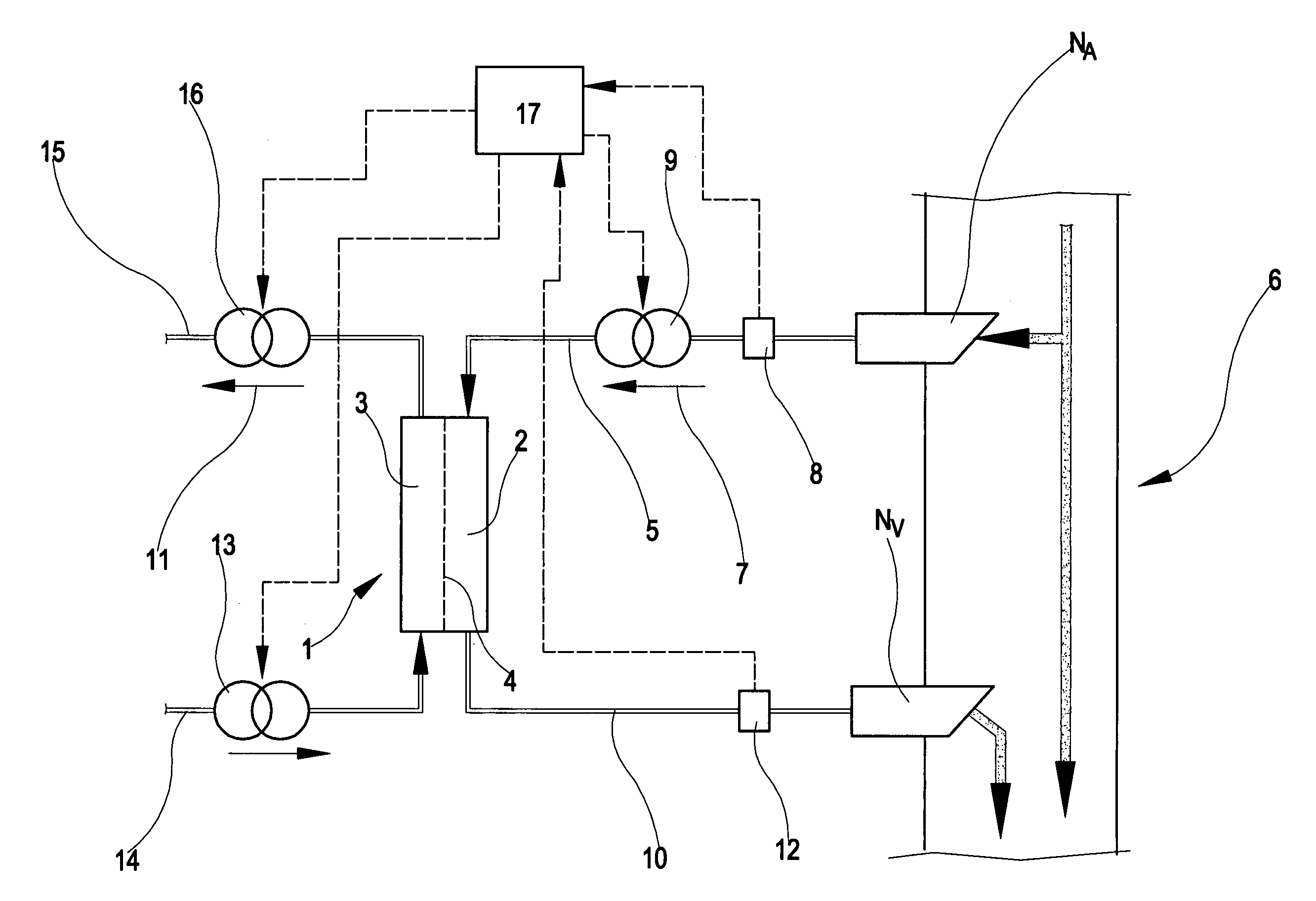
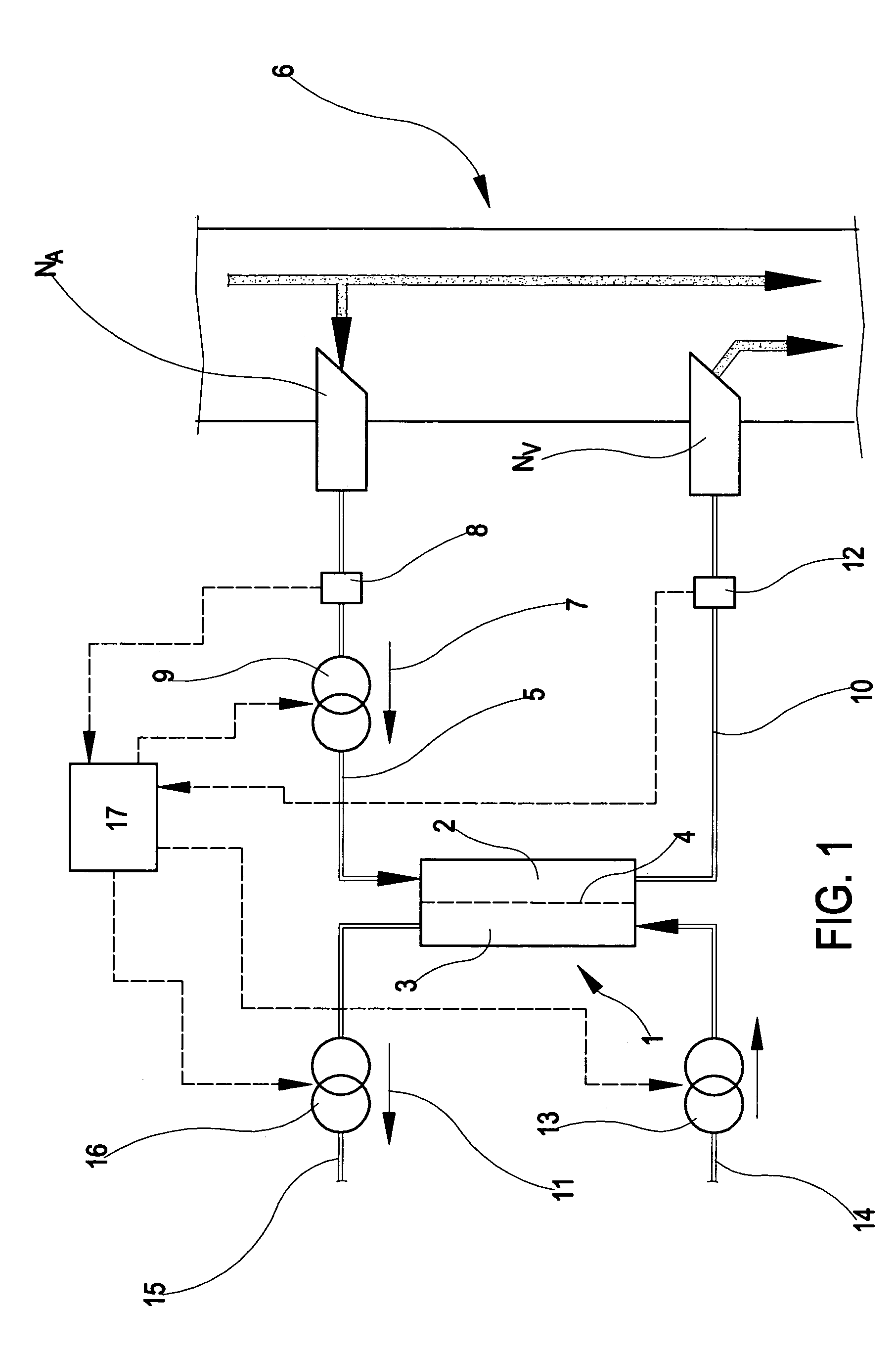
[0331]This example uses the above-described first monitoring procedure, applied to the apparatus of FIG. 1.

[0332]Direct measurement of pressures Pa, Paf, Pvf were taken at different flow rate values qb. The measurements taken are reported in the following table.

[0333]

qbPaPafPvfΔPf(ml / min)(mmHg)(mmHg)(mmHg)(mmHg)300100514292005241111005440144005142950050437

[0334]The equation of the straight line interpolating points ΔPf is as follows (see FIG. 4, where ΔPf is a function of qb)

ΔPf=0.016·(925−qb)

[0335]From which the following values are calculated

[0336]Rf=0.016 mmHg min / ml

[0337]qa=925 ml / min

[0338]From the third equation of the mathematical model used (assuming Pv=0) we have qb1=300 ml / min:

[0339]Rv=Pvf1qa=0.045⁢⁢mm⁢⁢Hg·min⁢ / ⁢ml

[0340]Given Pa=100 mmHg, for qb1=300 ml / min we obtain:

[0341]Rd=Pa-Paf1qa=0.053⁢⁢mm⁢⁢Hg·min⁢ / ⁢ml

second example

[0342]The second example uses the fourth monitoring procedure.

[0343]In the following the values of the pressure measured at different blood pump flow rates are reported.

[0344]

qbPaPafPvfPv(ml / min)(mmHg)(mmHg)(mmHg)(mmHg) 012062350150118593725011757373501145338

[0345]From these values we obtain:

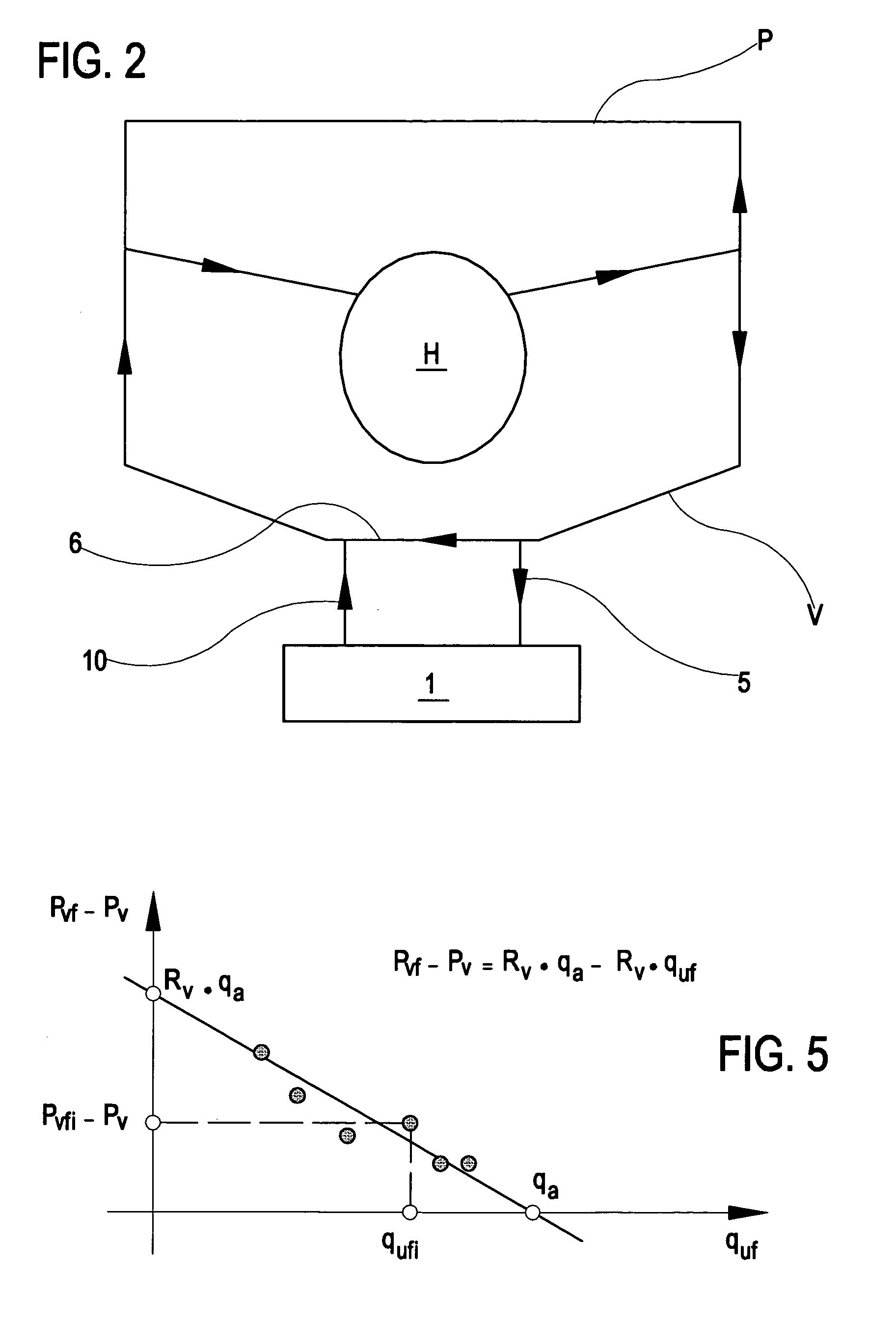
[0346]ca0=Paf0-Pv0Pa0-Pv0=0.52cv0=Pvf0-Pv0Pa0-Pv0=0.29

[0347]By applying a linear regression algorithm to the following equation:

Pafi−ca0·Pai−(1−ca0)·Pv0=ca1·qbi

[0348]the following value for coefficient ca1 was found:

[0349]ca1=−0.0155

[0350]After which the following resistance values were found:

[0351]Rd=0.069 mmHg min / ml

[0352]Rf=0.032 mmHg min / ml

[0353]Rf=0.042 mmHg-min / ml

[0354]From this we calculated:

[0355]qa=Paf0-Pvf0Rf=842⁢⁢ml⁢ / ⁢min


PUM

PropertyMeasurementUnit
Vapor pressureaaaaaaaaaa
Pressureaaaaaaaaaa
Flow rateaaaaaaaaaa

Abstract

In the apparatus and method for monitoring a vascular access (6) of an extracorporeal circuit (5; 10) of a patient, a control and calculation unit (17) varies a flow rate of a blood pump (9) predisposed to cause blood to circulate in the extracorporeal circuit. The control and calculation unit receives the pressure values in the blood withdrawal line (5) and the blood return line (10) from two pressure sensors (8, 12); the pressure values are a series of different values of the blood flow rate. The control and calculation unit processes the data gathered by means of a mathematical model which describes the variation of pressure in the vascular access as a function of the flow rate, in order to determine the blood flow rate in the vascular access. The invention detects the presence and location of a stenosis at the vascular access of a patient subjected to a hemodialysis treatment.

Description

CROSS REFERENCE TO RELATED APPLICATIONS[0001]This application claims the priority of Italian Patent Application No. M02003 A 000018, filed on Jan. 28, 2003, and the benefit of U.S. Provisional Application No. 60 / 466,052, filed on Apr. 29, 2003, the contents of which are incorporated herein by reference.BACKGROUND OF THE INVENTION [0002]The invention relates to a system for monitoring vascular access in a patient undergoing extracorporeal blood treatment.[0003]Specifically, though not exclusively, the invention can be usefully applied in the field of extracorporeal treatment for kidney failure.[0004]Setting up an extracorporeal blood treatment, such as for example hemodialysis therapy, requires blood circulation in an extracorporeal circuit connected to the cardiovascular circuit of the patient through a vascular access.[0005]The blood, taken from the patient and sent through an extracorporeal circuit, is subjected to a treatment, generally passing through a treatment unit (for examp...

Claims


Application Information

Patent Timeline
IPC IPC(8): A61M37/00A61M1/36C02F1/44
CPCA61M1/3621A61M1/3656A61M1/3663A61M1/3653A61M1/3639A61M1/3655A61M1/3623
Inventor CAVALCANTI, SILVIOLODI, CARLO ALBERTOFAVA, MASSIMO
Owner GAMBRO LUNDIA AB
Why Eureka
Try Eureka