
Improved one-way and two-way integrated valve for medical treatment

A combined valve, medical technology, applied in the direction of the valve, etc., can solve the problems of blockage, the normal flow rate of the drainage fluid is slow, and the weight is large.

Inactive Publication Date: 2013-12-25
丘奂阳 +2
View PDF6 Cites 3 Cited by
  • Summary
  • Abstract
  • Description
  • Claims
  • Application Information

AI Technical Summary

Problems solved by technology

The problem with this single-way combination valve for medical use in the prior art is that the pipe diameter of the cross pipe is consistent with the pipe joint and the pipe diameter of the valve body pipe, so that the inner pipe diameter of the annular converging section converges, thereby reducing the flow rate of the drainage fluid. The normal flow of the drainage fluid forms a resistance. In many cases, the flow of the drainage fluid is achieved by gravity, and the influence of the annular convergence section slows down the normal flow velocity of the drainage fluid.
Of course, in order to solve this problem, some manufacturers have taken measures to increase the diameter of the intersecting pipes. Through this measure, the diameter of the shrinking pipe of the annular converging section is equal to or close to the diameter of the pipe joint and the pipe of the valve body. Although the measure solves the influence of the circular converging section on the flow rate of the drainage fluid under normal circumstances, when the diameter of the intersecting pipe increases, the barrier ball needs a correspondingly larger diameter, and the barrier ball with a larger diameter will obviously have a larger Weight, as mentioned above, in many cases, the flow of drainage fluid is achieved by gravity, and the flow velocity of drainage fluid is generally not too high. When the valve is inverted, that is, when the converging mouth of the annular converging section is located above the vertical direction, the flow velocity of the drainage fluid often cannot push the barrier ball, resulting in failure. In addition, in the prior art, the function of the isolation net is to limit the barrier ball. Position, so that it is located in the ring-shaped convergence section, but the isolation net also forms resistance to the drainage fluid, especially when the concentration of the drainage fluid is relatively high, blockage may be formed at the position of the isolation net; moreover, although some manufacturers' instructions require CN201220087551 .2 The medical single-two-way combination valve disclosed in 2 is fixed according to the marked direction during use, but in the specific and medical process, the nurse will also fix this single-two-way combination valve according to the requirements of the instructions, but the patient's Movement or some other reasons often lead to this kind of fixed failure. After the fixed failure, the single- and two-way combination valve is in a non-fixed state. Obviously, in the non-fixed state, the inversion of the medical single- and two-way combination valve disclosed in CN201220087551.2 Appearance is inevitable, as mentioned above, after the inversion, it is more likely that the flow rate of the extradition fluid cannot overcome the gravity of the barrier ball and fail; There is a clearance fit between the valve core and the valve body. At the same time, the size of the matching surface is relatively large. During the process of the valve core rotating relative to the valve body, there is a greater risk of pollutants in the gap being brought into the drainage tube. Furthermore, The medical single-way combination valve disclosed in CN201220087551.2 has a spool with a cross and intercommunicated cross pipes, and one of the cross pipes has an annular converging section. Big trouble, the core-pulling structure of the injection mold will be very complicated, which directly leads to an increase in the cost of the product. In summary, it is obvious that there is a need for further improvement in the existing technology

Method used


Image

  • Improved one-way and two-way integrated valve for medical treatment
  • Improved one-way and two-way integrated valve for medical treatment
  • Improved one-way and two-way integrated valve for medical treatment

Examples


Embodiment Construction

[0032] The invention will be further described below in conjunction with the improved medical single-bidirectional combination valve provided by the preferred embodiments of the invention and the accompanying drawings.

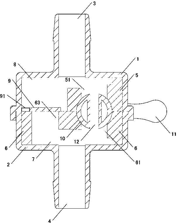
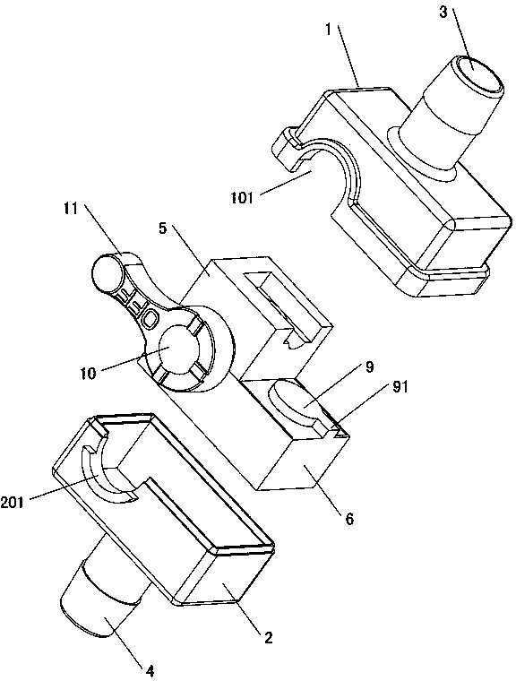
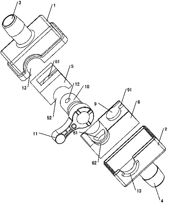
[0033] The improved medical single and two-way combination valve provided by the preferred embodiment of the present invention, as attached figure 1 , attached figure 2 , attached image 3As shown, it includes a valve body and a valve core. The valve body is provided with an inlet pipe joint 4 and an outlet pipe joint 3. The main point is that the valve body includes an upper shell 1 and a lower shell 2. The introduction pipe joint 4 and the The outlet pipe joint 3 is respectively arranged on the bottom surface of the lower casing 2 and the top surface of the upper casing 1, and the valve core is composed of an upper valve core 5, a lower valve core 6 and a valve shaft 10, and the lower valve core 6 is set In the lower housing 2, a lower transition channel ...


PUM


Abstract

The invention provides an improved one-way and two-way integrated valve for medical treatment. The valve comprises a valve body and a valve element, wherein a lead-in pipe joint and a lead-out pipe joint are arranged on the valve body. The integrated valve is characterized in that the valve body comprises an upper shell and a lower shell; the valve element comprises an upper valve element, a lower valve element, a third through hole communicated with an upper transition passage and a lower transition passage, and a one-way valve which is formed in the third through hole and comprises a diaphragm; a valve rotating shaft in the valve element is used for controlling the communication of the upper transition passage and the lower transition passage. Compared with the prior art, the one-way and two-way integrated valve works reliably, the flowing speed of drainage liquid cannot be influenced, the working state is independent of position, and the die is simple, convenient to assemble and low in cost.

Description

technical field [0001] The invention relates to an improved single- and two-way combined valve for medical use, which can be used in conjunction with various drainage tubes to control the drainage direction. Background technique [0002] The application of various drainage tubes is very common in the modern medical process. As we all know, in different treatment processes, sometimes the liquid needs to flow in two directions, and sometimes it needs to be restricted so that the liquid can only flow in one direction, so as to prevent the liquid from flowing backward and causing infection. The one-way drainage tube commonly used in medical institutions is mostly a one-way drainage tube, which is provided with a one-way valve in the pipeline formed by the drainage tube, and the two-way flow of liquid is restricted by the effect of the one-way valve. In clinical treatment work, it is often necessary to switch from one-way drainage to two-way drainage. The conventional practice is...

Claims


Application Information

Patent Timeline
IPC IPC(8): A61M39/22
Inventor 丘奂阳吴旭生张毅俊
Owner 丘奂阳
Learn More