

Casting technology capable of reducing hardness difference of traction wheel rope groove face
A casting process and traction sheave technology are applied in the field of casting process to reduce the hardness difference of the rope groove surface of the traction sheave. Poor, the temperature difference is not big, the effect of improving product quality
- Summary
- Abstract
- Description
- Claims
- Application Information
AI Technical Summary
Problems solved by technology
Method used
Image

Examples
Embodiment Construction
[0021] The preferred embodiments of the present invention will be described in detail below with reference to the accompanying drawings.
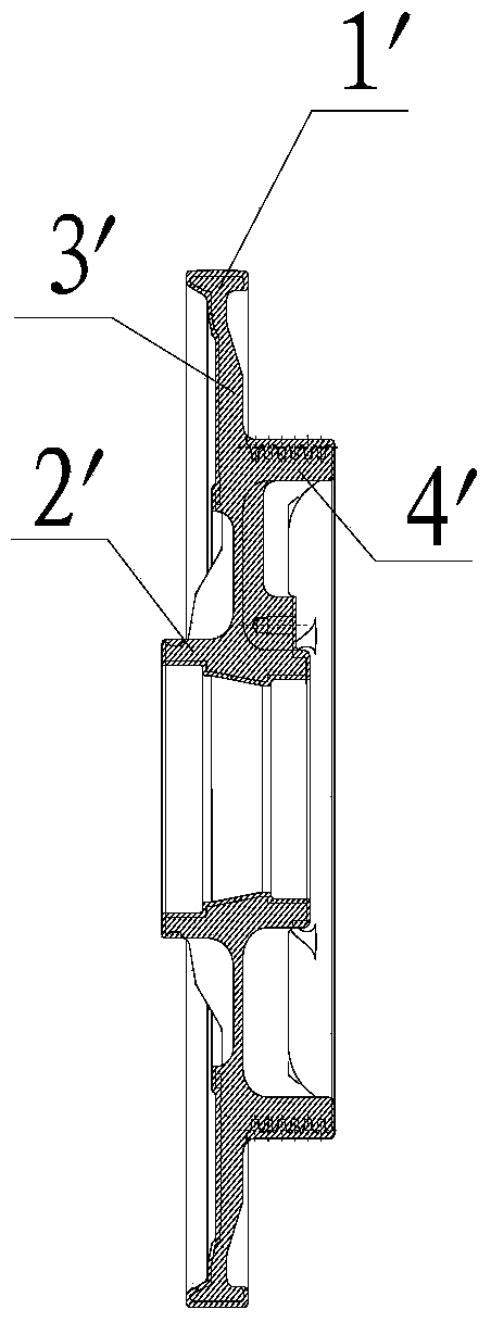
[0022] Using the casting process of the present invention to reduce the hardness difference of the rope groove surface of the traction sheave, such as figure 1 The traction sheave shown comprises the following steps:
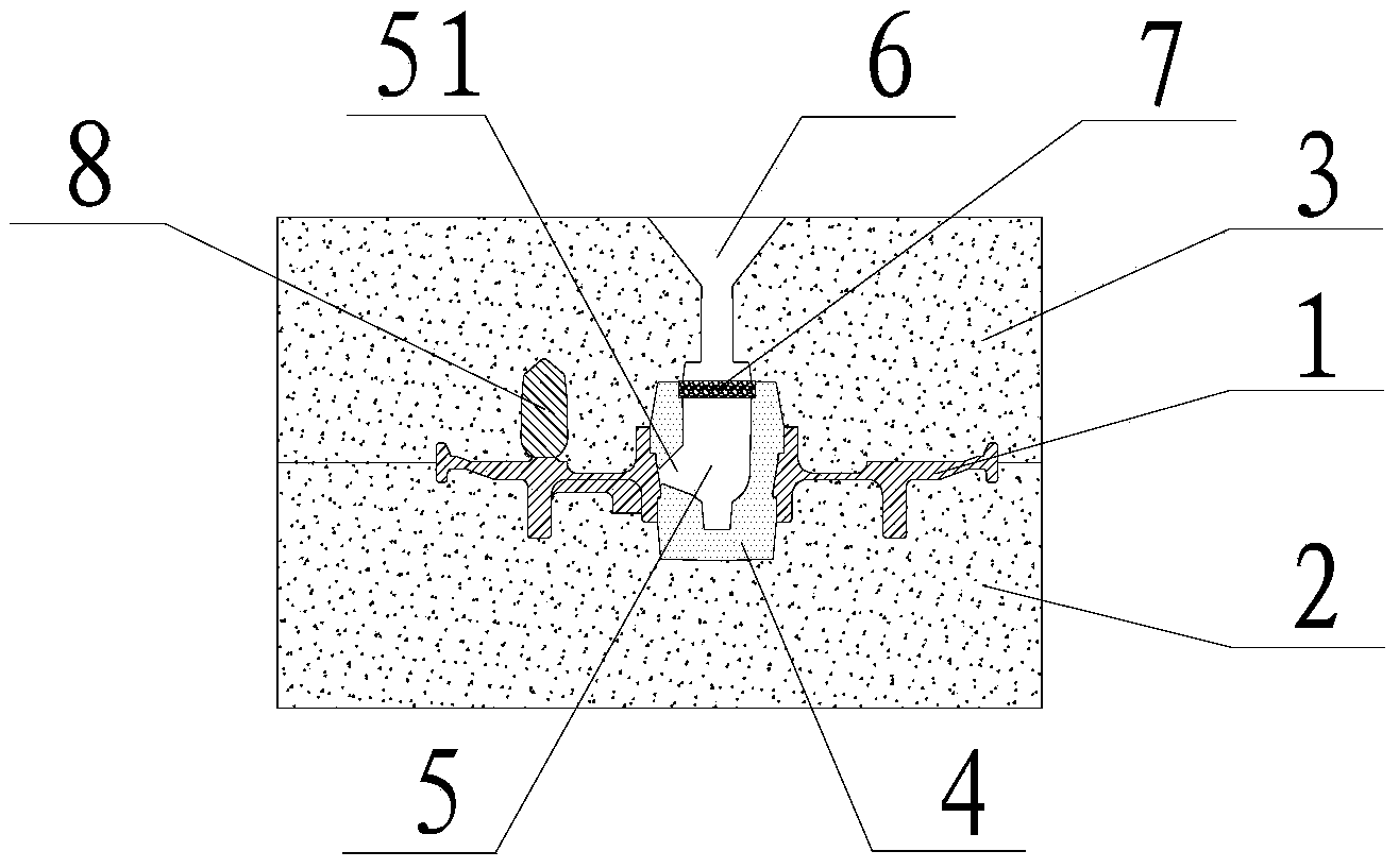
[0023] (a) Make the upper sand box: fix the mold with the same size and shape as the traction wheel on the formwork, heat the mold to 30~50°C and spray a release agent on its surface, then place the upper box and fill it with molding sand, 100~120N / cm 2 Mechanical compaction is carried out under pressure, and the mold can be put on the sand box;
[0024] (b) Make the lower sand box: turn the fixed mold 180°, repeat step (a) to get the lower sand box;
[0025] (c) Core making: install the core box matching the traction wheel on the core shooter, open the mold to clean the core box and spray the mold release agent, then clos...
PUM
 Abstract
Description
Claims
Application Information