Luffing mechanism for construction machinery and construction machinery

A technology of construction machinery and luffing mechanism, which is applied in building construction, building material processing, construction, etc., can solve the problems of insufficient use of oil cylinder force, large selection of luffing oil cylinders, and thick structure, so as to reduce the cost of oil cylinders. , Reduce design and manufacturing requirements, the effect of weight change

Active Publication Date: 2016-08-17
SANY AUTOMOBILE MFG CO LTD
View PDF4 Cites 0 Cited by
  • Summary
  • Abstract
  • Description
  • Claims
  • Application Information

AI Technical Summary

Problems solved by technology

In order to ensure safety, the design of the oil cylinder must meet the demand of the cylinder force when it is close to 0°, which leads to a large selection of the luffing oil cylinder 3', a thick, heavy structure, and high cost. power underutilized

Method used


Image

  • Luffing mechanism for construction machinery and construction machinery
  • Luffing mechanism for construction machinery and construction machinery
  • Luffing mechanism for construction machinery and construction machinery

Examples


Embodiment Construction

[0035] It should be noted that, in the case of no conflict, the embodiments of the present invention and the features in the embodiments can be combined with each other. The present invention will be described in detail below with reference to the accompanying drawings and examples.

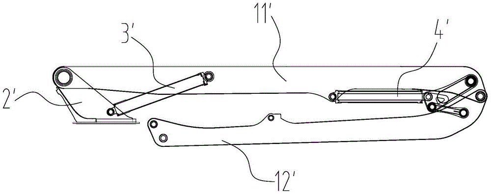
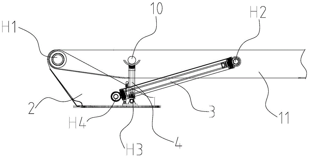
[0036] image 3 and Figure 4 Shown is a schematic diagram of the installation of a luffing mechanism used in construction machinery according to an embodiment of the present invention, wherein image 3 It is the state diagram when the boom is folded, Figure 4 It is the state diagram when the boom is deployed. The luffing mechanism of this embodiment is installed on a construction machine. The construction machine includes at least an arm frame and a mounting part 2 . The jib is a multi-section structure, including at least two section arms, and the adjacent section arms are connected end-to-end. The bottommost section is the first section arm 11, and the uppermost section is the second sec...


PUM


Abstract

The invention discloses a luffing mechanism for construction machinery and construction machinery. The luffing mechanism includes a luffing oil cylinder and a telescopic mechanism, the luffing oil cylinder is hinged between the first joint arm and the installation part; the telescopic mechanism is against the first joint arm and the installation part between the parts, and disengage from the first section arm or the installation part when the first section arm is unfolded to a preset angle. In the present invention, when the rotation angle of the boom frame is small, the force of the luffing cylinder can be shared by the telescopic mechanism, and when the rotation angle reaches a certain angle, the force is independently applied to the luffing cylinder, which can reduce the design and manufacturing requirements of the luffing cylinder, making the variable The bore of the oil cylinder becomes smaller, the weight becomes lighter, the cost is reduced, and its rated design pressure is fully utilized.

Description

technical field [0001] The present invention mainly relates to the technical field of engineering machinery, in particular to a luffing oil cylinder for engineering machinery and an engineering machine provided with the luffing oil cylinder. Background technique [0002] In construction machinery such as concrete pump trucks, concrete placing booms, concrete placing vehicles and wet spraying machines, multi-section boom systems are often used. like figure 1 As shown, this type of construction machinery includes no less than two joint arms, and the end-to-end connections between adjacent joint arms. From the root up, it is divided into the first section arm 11', the second section arm 12'... [0003] A turntable 2' can also be set on the engineering machinery, and the turntable 2' can rotate on a horizontal plane with respect to the fixed turret centered on a vertical line, and the turntable 2' can be used for installing and supporting the jib system. The root of the first...

Claims


Application Information

Patent Timeline
Patent Type & Authority Patents(China)
IPC IPC(8): E04G21/04
Inventor 朱红田润利谭海波
Owner SANY AUTOMOBILE MFG CO LTD
Why Eureka
Try Eureka