Piezoelectric extrusion type magnetorheological clutch and transfer torque calculating method of piezoelectric extrusion type magnetorheological clutch

A squeeze and clutch technology, applied in the direction of fluid clutch, clutch, calculation, etc., can solve the occasions that cannot be used to transmit large torque and limited use space, clutch transmission performance and service life decline, magnetorheological The clutch is easy to leak and other problems, to achieve the effect of good sealing, enhanced torque transmission capacity, and elimination of slip process

Inactive Publication Date: 2013-12-25
ZHEJIANG NORMAL UNIVERSITY
View PDF12 Cites 16 Cited by
  • Summary
  • Abstract
  • Description
  • Claims
  • Application Information

AI Technical Summary

Problems solved by technology

[0003] At present, the existing magneto-rheological clutches at home and abroad can be divided into cylinder/disc type, such as foreign patents: a single-disc magneto-rheological fan clutch disclosed in U.S.5896965, a multi-disc magneto-rheological clutch disclosed in U.S. Patent5823309; Patents: a single-plate three-disc magneto-rheological clutch disclosed in CN101915277A, a radial self-pressurized magneto-rheological fluid clutch disclosed in ZL00104451.6, a centrifugal magnetorheological fluid clutch disclosed in ZL01137376.6, etc., all have structural It is simple, quick in response and strong in versatility, but there are some deficiencies, such as: ①Torque transmission of barrel/disc

Method used


Image

  • Piezoelectric extrusion type magnetorheological clutch and transfer torque calculating method of piezoelectric extrusion type magnetorheological clutch
  • Piezoelectric extrusion type magnetorheological clutch and transfer torque calculating method of piezoelectric extrusion type magnetorheological clutch
  • Piezoelectric extrusion type magnetorheological clutch and transfer torque calculating method of piezoelectric extrusion type magnetorheological clutch

Examples


Embodiment Construction

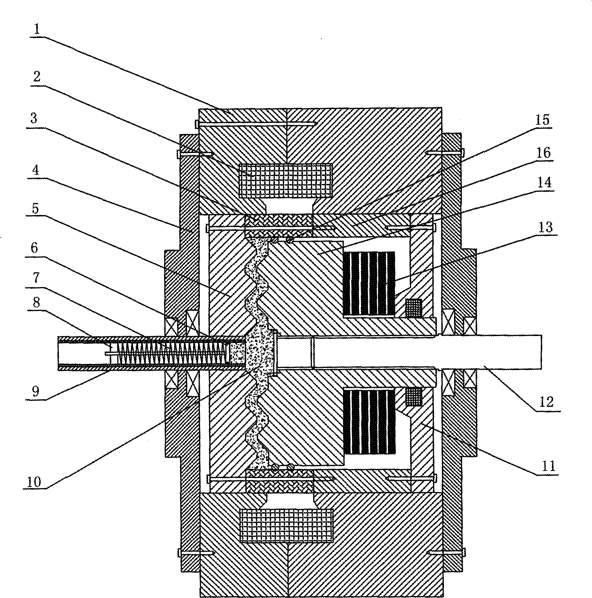
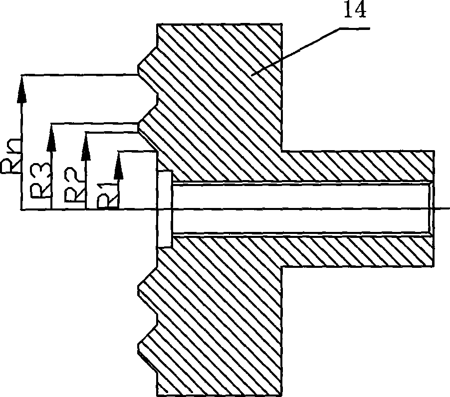
[0020] refer to figure 1 , figure 2 It is an embodiment of the piezoelectric extrusion magneto-rheological clutch and its transmission torque calculation method of the present invention. The piezoelectric extrusion magneto-rheological clutch includes a housing 1 provided with a cylindrical through hole, and the housing 1 The two ends are respectively provided with outer end caps 4 that close the through holes, and the coil 2 is arranged in the housing 1, and the driving disk 5 and the driven disk 14 are arranged in the said through holes, and the driving disk 5 and the driven disk 14 is provided with a magnetorheological fluid 10, and the working surface of the driving disk 5 is provided with at least two circles of concentric convex strips, the convex strips are concentric with the driving disk 5, and the working surface of the driven disk 14 is provided with At least two circles of grooves adapted to the protruding strips. The driving disk 5 is connected with the driving s...


PUM


Abstract

The invention discloses a piezoelectric extrusion type magnetorheological clutch, which comprises a casing with a cylindrical through hole, wherein a coil is arranged in the casing, a driving disc and a driven disc are arranged in the through hole, magnetorheological fluid is arranged between the driving disc and the driven disc, the work surface of the driving disc is provided with at least two circles of concentric convex strips, the work surface of the driven disc is provided with at least two circles of grooves matched with the convex strips, a stacked piezoelectric drive used for driving the driven disc to move towards the driving disc in an axial direction is arranged on the driven disc, and a fine adjustment device used for accommodating redundant magnetorheological fluid is arranged on a driving shaft. A transfer torque calculating method of the piezoelectric extrusion type magnetorheological clutch is characterized in that the transfer torque T extrusion of the clutch is shown as the accompanying drawing. The piezoelectric extrusion type magnetorheological clutch has the advantages that a piezoelectric stacked actuator extrudes the magnetorheological fluid, and the shear yield stress of the magnetorheological fluid can be improved, so the torque transfer capability is greatly enhanced, the energy consumption is low, the transfer capability control capability of the clutch is high, and the sealing performance is good.

Description

technical field [0001] The invention relates to a piezoelectric extrusion magneto-rheological clutch and a method for calculating the transmission torque thereof. Background technique [0002] The magneto-rheological clutch realizes the combination and separation functions of the master / slave parts through the control of the strength of the external magnetic field, and even realizes the stepless change control of the torque transmission. It overcomes the shortcomings of traditional electromagnetic / magnetic powder / friction clutches such as easy wear and high noise, and has attracted scholars and scholars at home and abroad for its advantages of simple structure, no mechanical wear, low noise, quick response (within 10 milliseconds), and low energy consumption. Extensive research in industry has made remarkable progress in recent years. [0003] At present, the existing magneto-rheological clutches at home and abroad can be divided into cylinder / disc types, such as foreign pa...

Claims


Application Information

Patent Timeline
IPC IPC(8): F16D37/02G06F19/00
Inventor 王鸿云阚君武刘卫东
Owner ZHEJIANG NORMAL UNIVERSITY
Why Eureka
Try Eureka