A high-speed switching valve

A high-speed switching valve and valve body technology, applied in multi-port valves, valve devices, engine components, etc., can solve problems such as leakage, affect system efficiency, and small flow capacity, achieve good manufacturability and reduce transient hydraulic power. , the effect of avoiding leakage

Active Publication Date: 2015-09-02
ZHEJIANG UNIV
View PDF5 Cites 0 Cited by
  • Summary
  • Abstract
  • Description
  • Claims
  • Application Information

AI Technical Summary

Problems solved by technology

[0004] In order to reduce the influence of hydraulic power, traditional high-speed on-off valves mostly adopt symmetrical ball valve or cone valve design, and realize P-A or A-T state switching through electromagnet drive. Due to the limitation of electromagnet output force, the switching frequency is basically lower than 50Hz, and the valve Due to the design of the ball valve and the cone valve, there will be a transition section where the P port, the A port, and the T port are all open. If the high-speed switching valve is switched on and off frequently, this transition section will cause a large amount of leakage. Seriously affect system efficiency

Method used


Image

  • A high-speed switching valve
  • A high-speed switching valve
  • A high-speed switching valve

Examples


Embodiment Construction

[0016] The present invention will be further described below in conjunction with accompanying drawing and example.

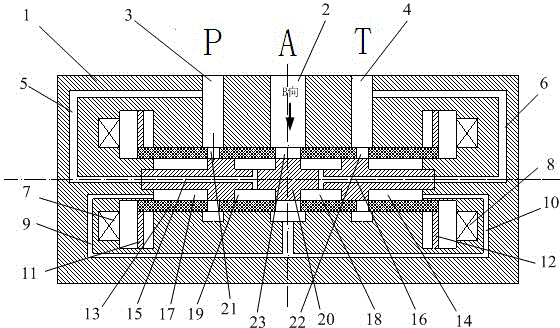
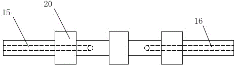
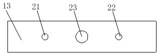
[0017] Such as figure 1 , figure 2 , image 3 As shown, the present invention includes valve body 1, A port 2, P port 3, T port 4, pressure oil drainage channel 5, oil return drainage channel 6, left electromagnet 7, right electromagnet 8, left drainage channel 9, right Drainage channel 10, left armature 11, right armature 12, valve sleeve 13, auxiliary oil return valve cavity 14, spool left drainage channel 15, spool right drainage channel 16, auxiliary pressure valve cavity 17, main oil return valve cavity 18, The main pressure valve cavity 19, and the main valve core 20, the flow hole P21, the flow hole T22, the flow hole A23; the main valve core 20 and the valve sleeve 13 are sequentially installed in the center hole of the valve body 1, and the valve sleeve 13 is connected with the main valve sleeve. The spool 20 is sliding fit, the two ends of the main...


PUM


Abstract

The invention discloses a high-speed switch valve. A valve sleeve and a main spool are arranged coaxially. Two ends of the main spool are connected with a valve body. A left armature and a right armature are connected with two ends of the valve sleeve. The left end of the main spool is provided with a spool left drainage channel whereby a main pressure cavity is communicated with a port P. The right end of the main spool is provided with a spool right drainage channel whereby a main return oil cavity is communicated with a port T. A port A is communicated with an auxiliary pressure cavity and an auxiliary return oil cavity through the left and right drainage channels respectively. Opening and closing of the valve is switched through the valve sleeve; hydraulic force of the valve is reduced; the valve sleeve and the main spool are in sliding fit, so that leakage during switching is avoided; flow from the port P and the port A is doubly increased through the spool left drainage channel and the auxiliary pressure cavity, and transient hydraulic force borne by the valve sleeve is reduced. The high-speed switch valve has the advantages such as simple structure, high machinability and simplicity of operation; the valve can be opened and closed fast.

Description

technical field [0001] The invention relates to a switching valve, in particular to a high-speed switching valve. Background technique [0002] Electro-hydraulic digital control technology is an ideal method to realize high-speed and high-precision control of hydraulic systems. It is currently used in important fields such as automobiles, metallurgy, and engineering machinery. High-speed switching valve is an important part of electro-hydraulic digital control technology, and a key component to realize electro-hydraulic digital control. [0003] The switch valve is to change the on-off or flow direction of the fluid by opening and closing the valve port, and is the basic component of the hydraulic system. The main requirements for on-off valves are: fast response, low leakage, etc. [0004] In order to reduce the influence of hydraulic power, traditional high-speed on-off valves mostly adopt symmetrical ball valve or cone valve design, and realize P-A or A-T state switchin...

Claims


Application Information

Patent Timeline
Patent Type & Authority Patents(China)
IPC IPC(8): F16K11/065
Inventor 邹俊吉晨傅新
Owner ZHEJIANG UNIV
Why Eureka
Try Eureka