High-speed large-flow clearence slide valve

A large flow and gap technology, applied in the direction of sliding valves, valve devices, fuel injection pumps, etc., can solve the problems that valves are not widely used in engines and poor temperature adaptability, so as to increase the opening and closing speed and reduce the liquid at the valve port. The effect of high power and energy utilization

Inactive Publication Date: 2005-05-25
ZHEJIANG UNIV
View PDF0 Cites 0 Cited by
  • Summary
  • Abstract
  • Description
  • Claims
  • Application Information

AI Technical Summary

Problems solved by technology

This driving method requires the design of a displacement amplification device; and it has poor adaptability to temperature; it is not suitable for occasions with severe vibration
Therefore, this valve is not widely used in engines at present.

Method used


Image

  • High-speed large-flow clearence slide valve
  • High-speed large-flow clearence slide valve
  • High-speed large-flow clearence slide valve

Examples


Embodiment Construction

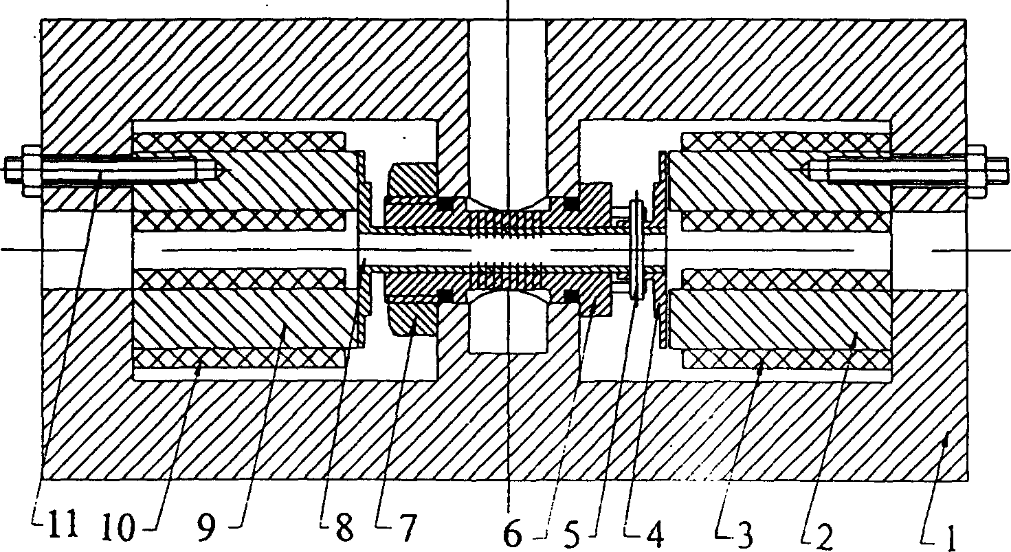
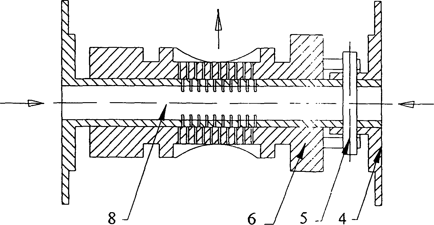
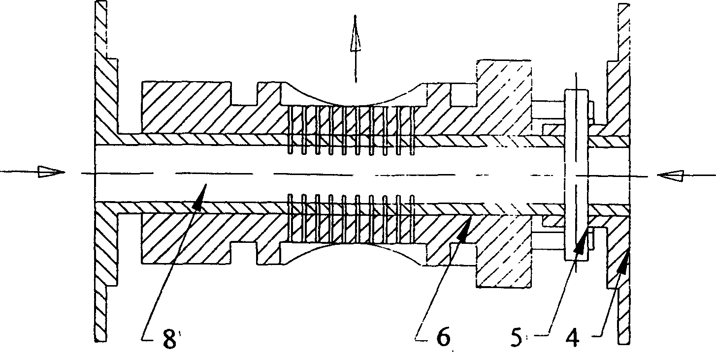
[0010] Such as figure 1 As shown, two snap-fit ​​electromagnets are symmetrically installed in the valve body 1 cavity at both ends of the hollow valve core 8, and the two snap-fit ​​electromagnets are respectively fixed with connecting screws 11 installed on the valve body, and the valve core 8 is covered with a valve Sleeve 6, valve sleeve 6 is fixed between the two cavities of valve body 1 with fastening screw 7, one end of spool 8 can be clutched with the clapping type electromagnet at one end, and the other end of spool 8 is equipped with magnetic pole 4, with a pin 5 is connected with the spool 8 as a whole, and the magnetic pole 4 can be clutched with the snap-on electromagnet at the other end; the mating surfaces of the spool 8 and the valve sleeve 6 are respectively opened with the same number, the same width, and the same distance between non-circumferential gaps. The valve port is connected with the oil outlet of valve body 1.

[0011] The working principle of the ...


PUM


Abstract

The invention discloses a high-speed and large-flow slot slide valve. Install two snap-fit ​​electromagnets symmetrically in the valve body cavity at both ends of the valve core. The hollow valve core is covered with a valve sleeve. One end of the valve core can be clutched with the snap-fit ​​electromagnet at one end, and the other end of the valve core is equipped with a magnetic pole. , the magnetic pole can be clutched with the snap-on electromagnet at the other end, the valve core and the valve sleeve have the same number, the same width, and the same distance between the non-circumferential gap-shaped valve ports on the mating surface, the valve port and the oil outlet of the valve body connected. The hollow valve core structure is adopted to reduce the mass of the moving parts; the driving force of the valve core movement is generated by the opposite clapping electromagnet, and the energy utilization rate of the electromagnet is high; , which reduces the movement distance of the valve core when it is opened and closed; at the same time, this gap valve port can reduce the hydraulic power of the valve port. Therefore, the sliding valve structure adopted in the present invention can increase the opening and closing speed of the valve core under the premise of ensuring a certain flow rate.

Description

technical field [0001] The invention relates to a slide valve, in particular to a high-speed, large-flow gap slide valve. Background technique [0002] As the engine has higher and higher requirements for environmental protection and energy saving, the high-pressure common rail fuel injection system has gradually become the development direction of the engine fuel system. As one of the core components of the high-pressure common rail fuel injection system, the high-speed and large-flow valve has become the focus of attention of all parties. The research and development of high-speed and large-flow valves mainly focuses on the drive mode of the valve core and the structure of the valve port. [0003] From the drive mode of the spool: there are electromagnet, magnetostrictive material or piezoelectric crystal material deformation drive and memory alloy material drive. The deformation drive of magnetostrictive material or piezoelectric crystal mate...

Claims


Application Information

Patent Timeline
Patent Type & Authority Patents(China)
IPC IPC(8): F02M51/06F02M59/46F16K3/314
Inventor 徐兵周盛杨华勇
Owner ZHEJIANG UNIV
Why Eureka
Try Eureka