Heat dissipation device and illumination device provided with same

A heat dissipation device and lighting device technology, applied in lighting devices, cooling/heating devices of lighting devices, lighting and heating equipment, etc., can solve problems such as cumbersome assembly, high cost, and complicated manufacturing process of reflectors

Inactive Publication Date: 2013-12-25
OSRAM GMBH
View PDF0 Cites 1 Cited by
  • Summary
  • Abstract
  • Description
  • Claims
  • Application Information

AI Technical Summary

Problems solved by technology

[0003] However, the common disadvantage of the above-mentioned two types of reflectors in the prior art is that the manufacturing process of these two reflectors is complicated and the cost is high
At the same time, these two reflectors are separate parts, which need to be separately assembled to the corresponding positions of the lighting device, so their assembly is relatively cumbersome.

Method used


Image

  • Heat dissipation device and illumination device provided with same
  • Heat dissipation device and illumination device provided with same
  • Heat dissipation device and illumination device provided with same

Examples


Embodiment Construction

[0026] In the following detailed description, reference is made to the accompanying drawings which form a part hereof, and in which are shown by way of illustrations specific embodiments in which the invention may be practiced. With respect to the figures, directional terms such as "bottom", "upper", "inner", etc. are used with reference to the orientation of the figures being described. Since components of embodiments of the present invention may be placed in many different orientations, the orientation terms are used for illustration only and not in any limiting sense. It is to be understood that other embodiments may be utilized and structural or logical changes may be made without departing from the scope of the present invention. Therefore, the following detailed description should not be taken in a limiting sense, and the invention is defined by the appended claims.

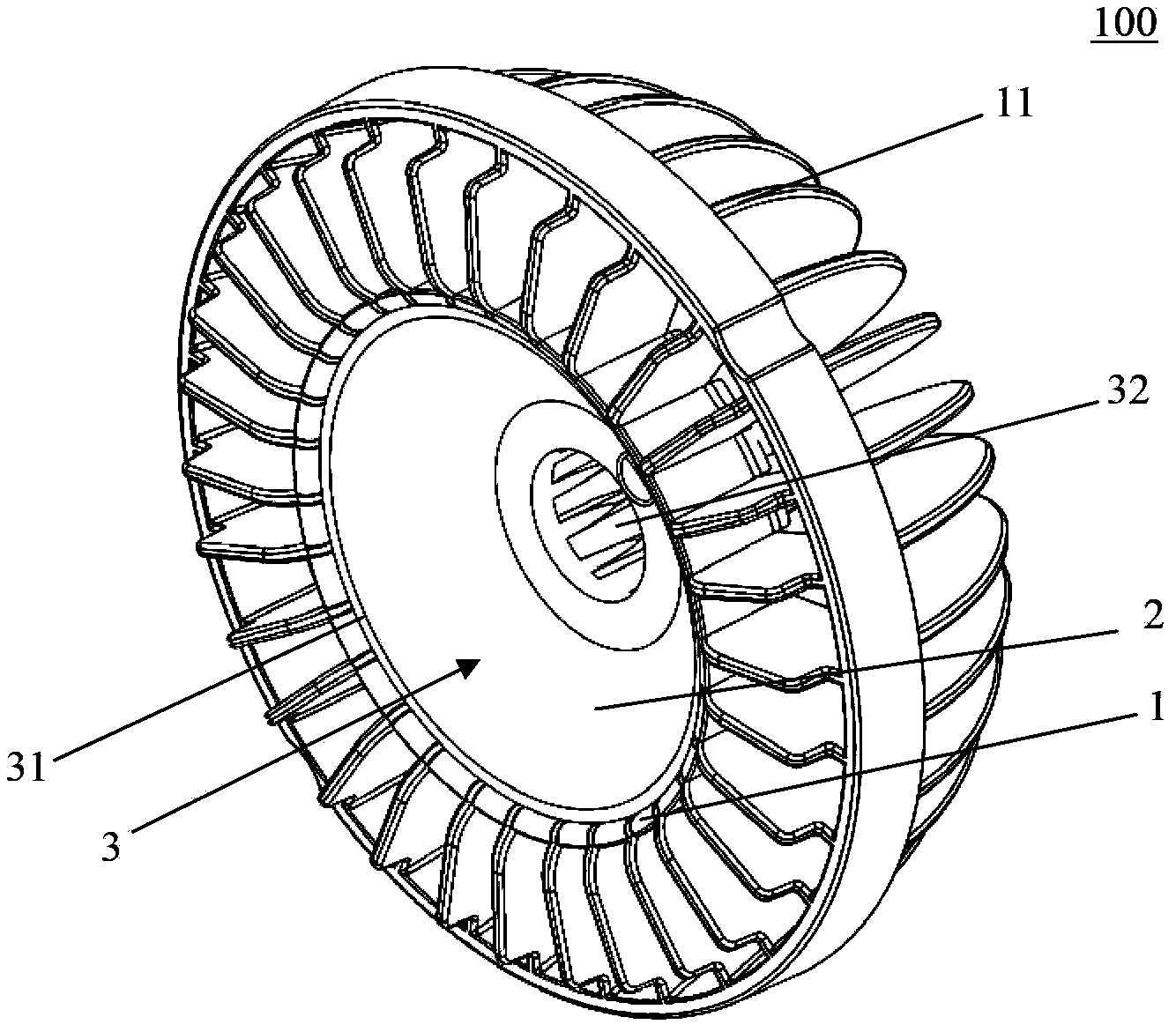
[0027] figure 1 A schematic diagram of the heat dissipation device 100 according to the first embodime...


PUM


Abstract

The invention relates to a heat dissipation device (100) for an illumination device. The heat dissipation device (100) comprises a base body (1) and a reflector (2) integrally formed with the base body (1). Furthermore, the invention also relates to the illumination device provided with the heat dissipation device (100).

Description

technical field [0001] The invention relates to a heat dissipation device for an illuminating device. In addition, the present invention also relates to an illuminating device with the heat dissipation device of the above type. Background technique [0002] In some traditional lighting devices and LED lighting devices, in order to meet different lighting requirements, it is usually necessary to equip the lighting devices with optical components, such as reflectors. However, the optical assembly is usually provided separately from the other components of the lighting device. When assembling the lighting device, it is usually necessary to separately assemble the optical components to the corresponding positions of the lighting device. In the prior art, plastics are usually used to make optical components, such as reflectors, through a precise injection molding process, and reflective coatings are coated on the reflectors, but the material of this reflector determines that it...

Claims


Application Information

Patent Timeline
Patent Type & Authority Applications(China)
IPC IPC(8): F21V29/00F21Y101/02F21V29/77F21Y115/10
Inventor 袁海平杨灿邦戴成龙叶泽生
Owner OSRAM GMBH
Why Eureka
Try Eureka