
Method for on-line temperature monitoring of exciting winding of plasma Hall effect thruster

A technology of excitation winding and Hall effect, applied in thermometers, thermometers and instruments with directly sensitive electrical/magnetic components, etc., can solve the problem of adding additional measuring couples, etc., and achieve the effect of simple structure and easy realization.

Inactive Publication Date: 2013-12-25
HARBIN INST OF TECH
View PDF5 Cites 17 Cited by
  • Summary
  • Abstract
  • Description
  • Claims
  • Application Information

AI Technical Summary

Problems solved by technology

[0004] The present invention aims to solve the problem that an additional measurement couple needs to be added for the online temperature monitoring of the excitation winding coil of the existing plasma Hall effect thruster. The present invention provides an online monitoring method for the excitation winding temperature of the plasma Hall effect thruster

Method used


Image

  • Method for on-line temperature monitoring of exciting winding of plasma Hall effect thruster
  • Method for on-line temperature monitoring of exciting winding of plasma Hall effect thruster
  • Method for on-line temperature monitoring of exciting winding of plasma Hall effect thruster

Examples


specific Embodiment approach 1

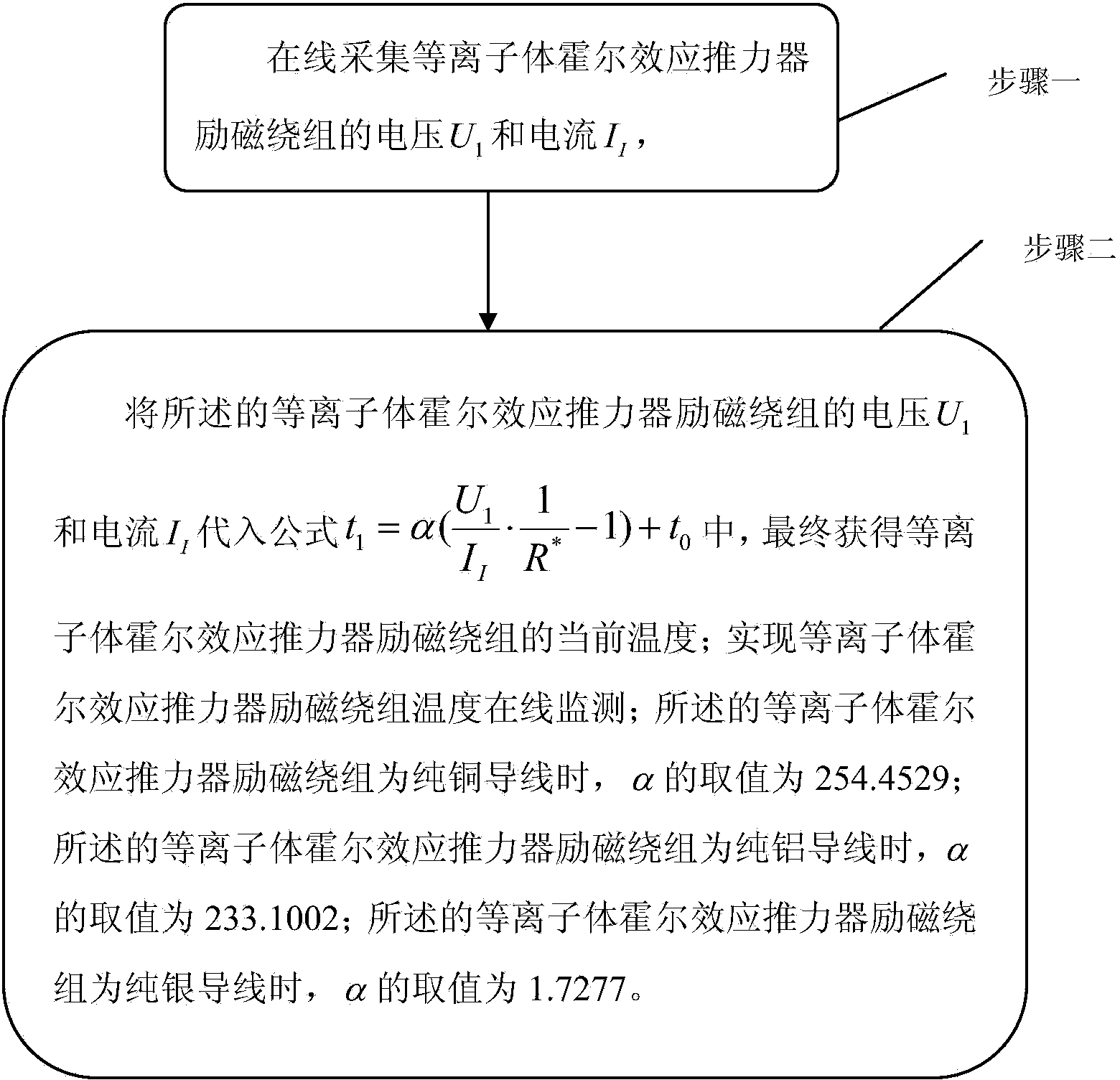
[0022] Specific implementation mode one: see figure 1 Illustrate this embodiment mode, the on-line monitoring method of excitation winding temperature of plasma Hall effect thruster described in this embodiment mode, its concrete steps are,

[0023] Step 1. Online collection of the voltage U of the excitation winding of the plasma Hall effect thruster 1 and current I I ,

[0024] Step 2, the voltage U of the excitation winding of the plasma Hall effect thruster 1 and current I I Into the formula

[0025] t 1 = α ( U 1 I I · 1 R * - 1 ) + t 0 - - - ( 1 ...

specific Embodiment approach 2

[0034] Specific implementation mode two: see figure 1 This embodiment is described. The difference between this embodiment and the online monitoring method for the excitation winding temperature of the plasma Hall effect thruster described in the first embodiment is that the online collection of the voltage U1 of the excitation winding of the plasma Hall effect thruster Implemented with voltage transformers.

specific Embodiment approach 3

[0035] Specific implementation mode three: see figure 1 This embodiment is described. The difference between this embodiment and the online monitoring method for the excitation winding temperature of the plasma Hall effect thruster described in the first or second specific embodiment is that the online collection of the excitation winding temperature of the plasma Hall effect thruster Current II is realized with a current transformer.

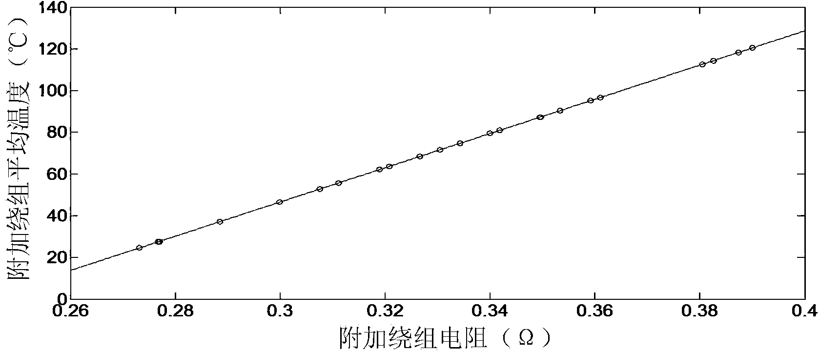
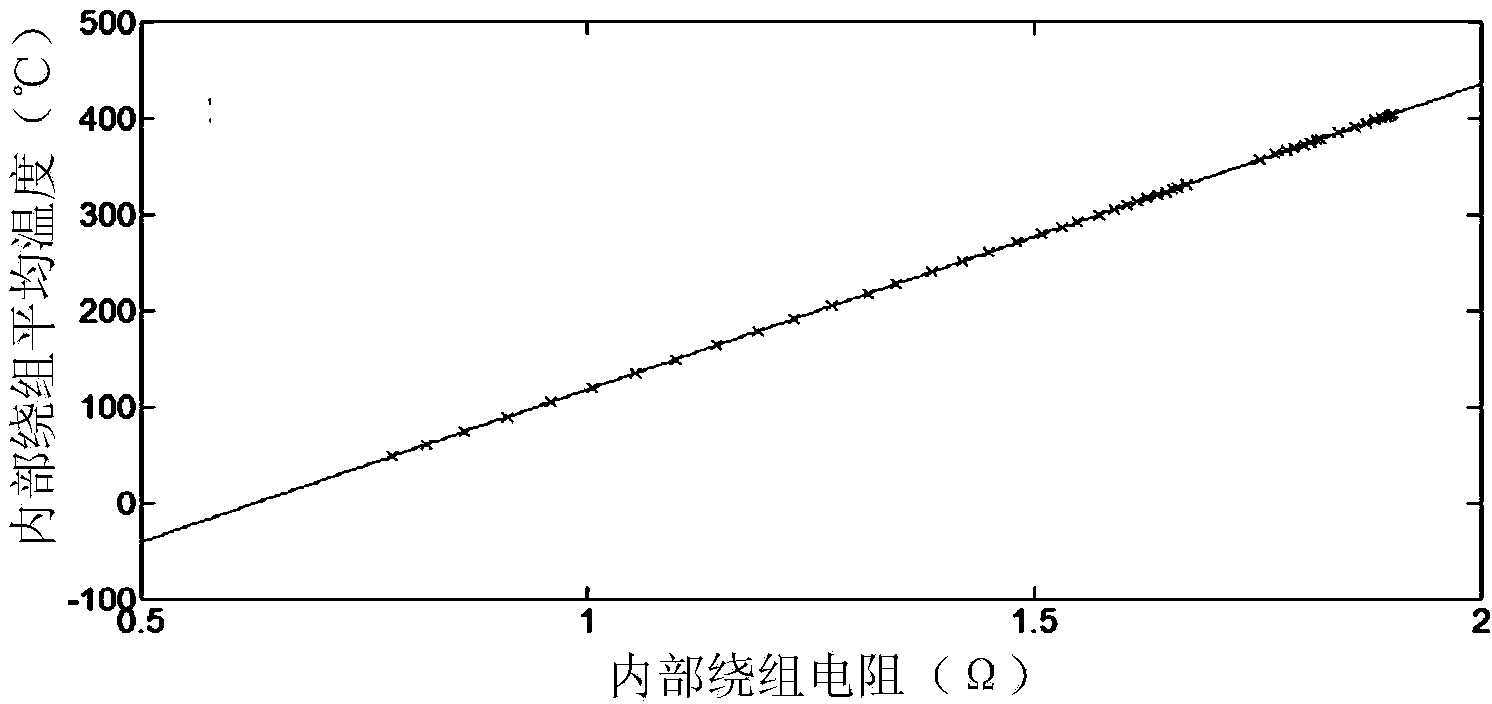
[0036] The resistance of all substances will change due to changes in temperature. For most metals and most alloys, the resistance increases with the increase of temperature. In the prior art, in order to reduce the difficulty of system design and improve reliability, There is no effective method for coil temperature monitoring of thruster space flight, but the present invention verifies the applicability of formula (1) in the range of 30 degrees to 500 degrees, without changing the overall design of the space propulsion system, The monitoring...


PUM


Abstract

The invention provides a method for on-line temperature monitoring of an exciting winding of a plasma Hall effect thruster, relates to the technical field of Hall effect thrusters and aims at solving the problem that the on-line temperature monitoring of the exciting winding of an existing plasma Hall effect thruster needs an additional measurement galvanic couple. The method comprises the specific steps of 1 acquiring voltage U1 and current II of the exciting winding of the plasma Hall effect thruster on line; 2 substituting the voltage U1 and the current II of the exciting winding of the plasma Hall effect thruster into a formula and finally obtaining the current temperature of the exciting winding of the plasma Hall effect thruster; achieving the on-line temperature monitoring of the exciting winding of the plasma Hall effect thruster. The method is specifically applied to the field of temperature measurement of the exciting winding of the plasma Hall effect thruster.

Description

technical field [0001] The present invention relates to the technical field of Hall effect thrusters. Background technique [0002] Microsatellites have small size, light weight, small moment of inertia, flexible launch methods, low cost, and short development cycle, which have become one of the development trends in the satellite field today. Satellite networking technology can reduce the complexity of each satellite and improve the reliability of the entire system, and the reduction in the size and weight of each satellite will also reduce the cost of satellite launch, which has been gradually applied to the commercial field. In order to achieve accurate positioning and attitude adjustment of micro-satellites, the requirements for the thrust system are small thrust and low power. , High efficiency, high specific impulse propulsion device requirements. The electric propulsion device accelerates the propellant gas through electric heating or the force of the electromagneti...

Claims


Application Information

Patent Timeline
IPC IPC(8): G01K7/16
Inventor 刘洪岩魏立秋杨子怡韩柯于达仁
Owner HARBIN INST OF TECH
Learn More