A light guide plate and a backlight module

A technology of light guide plate and light source, which is applied in the direction of light guide, optics, electric light source, etc., and can solve the problems of difficult preparation of syringe capacity injection mold, difficulty in large-scale, thick thickness, etc.

Active Publication Date: 2016-08-17
BEIJING BOE OPTOELECTRONCIS TECH CO LTD
View PDF8 Cites 0 Cited by
  • Summary
  • Abstract
  • Description
  • Claims
  • Application Information

AI Technical Summary

Problems solved by technology

[0004] In the two methods of the prior art, the large-sized light guide plate produced by extrusion is thicker and cannot meet the requirements of slim, while the injection method can meet the requirements of slim, but it is difficult to prepare due to the capacity of the injector and the injection mold , it is difficult to achieve large-scale

Method used


Image

  • A light guide plate and a backlight module
  • A light guide plate and a backlight module
  • A light guide plate and a backlight module

Examples


Embodiment 1

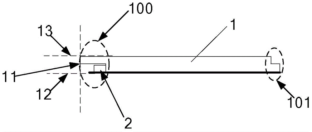
[0042] An embodiment of the present invention provides a light guide plate. The light guide plate includes several sub-light guide plates; the sub-light guide plates include a light incident surface, a reflection surface and a light exit surface. A light source groove is provided on the light incident surface of the sub-light guide plate, and the light source groove is used to place a light source; a connecting piece is provided on the opposite side of the light incident surface; wherein, the connecting piece is used for The sub-light guide plates in the light guide plates are connected to each other.

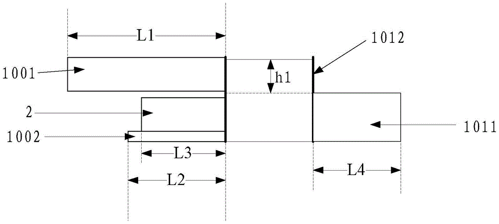
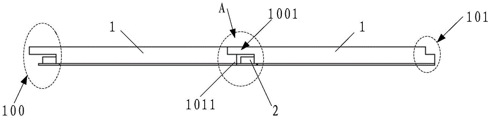
[0043] Optionally, a first connecting member may be provided on the side opposite to the light-incident surface, and the two sub-light guide plates may be assembled and connected by the first connecting portion of one sub-light guide plate and the light source groove of the other sub-light guide plate, In this way, a large-sized light guide plate can be assembled from small-siz...

Embodiment 2

[0058] Embodiments of the present invention provide a figure 1 The manufacturing method of the sub-light guide plate shown, the method includes:

[0059] S1, prepare and can form such as figure 1 and Figure 6 Injection mold for the shape of the sub-LGP shown.

[0060] S2. Using an injection device to inject light guide plate material into the injection mold to form a sub-light guide plate primary plate.

[0061] S3. Using methods such as lazer (laser), etching (etching) or indentation (indentation) to process light guide point patterns on the primary sub-light guide plate to form a sub-light guide plate.

Embodiment 3

[0063] An embodiment of the present invention provides a light guide plate. The light guide plate includes several sub-light guide plates; the sub-light guide plates include a light incident surface, a reflection surface and a light exit surface. A light source groove is provided on the light incident surface of the sub-light guide plate, and the light source groove is used to place a light source; connecting pieces are provided on two adjacent sides of the light incident surface; wherein, the connection The components are used to connect the sub-light guide plates in the light guide plate to each other.

[0064] Such as Figure 9 Shown is a top view of the sub-light guide plate 1, Figure 10 for Figure 9 A cross-sectional view of the sub-light guide plate shown in the direction A1-A2; Figure 11 for Figure 9 The shown sub-light guide plate is a cross-sectional view along the B1-B2 direction.

[0065] Such as Figure 10 As shown, the right side of the sub-light guide p...


PUM


Abstract

Embodiments of the present invention provide a light guide plate and a backlight module, which relate to the field of display technology and can achieve slimming and upsizing at the same time. The light guide plate includes: several sub-light guide plates; the sub-light guide plate includes a light incident surface, a reflection surface and a light exit surface; a light source groove is arranged on the light incident surface of the sub-light guide plate, and the light source groove is used for For placing the light source; on the side opposite to or adjacent to the light incident surface, a connection part is provided; wherein the connection part is used to connect the sub-light guide plates in the light guide plate to each other.

Description

technical field [0001] The invention relates to the field of display technology, in particular to a light guide plate and a backlight module. Background technique [0002] Liquid crystal displays have occupied a dominant position in the current flat panel display market due to their small size, low power consumption, and low radiation. In a liquid crystal display, the liquid crystal itself does not emit light, but is used to modulate the incident light from the backlight module to make the display display images. The backlight modules of liquid crystal display devices are mainly divided into direct-type backlight modules and edge-type backlight modules, and edge-type backlight modules are more suitable for slim (slim) and lightweight requirements of liquid crystal display devices due to their thin thickness and light weight. has received widespread attention. [0003] Recently, TV display devices are gradually developing towards larger sizes. Correspondingly, all parts of ...

Claims


Application Information

Patent Timeline
Patent Type & Authority Patents(China)
IPC IPC(8): G02B6/00F21S2/00
Inventor 姜太声权宁万
Owner BEIJING BOE OPTOELECTRONCIS TECH CO LTD
Why Eureka
Try Eureka