Machine for removing impurities on electric transmission line

A technology for power transmission lines and cleaning machines, which is applied to overhead line/cable equipment, cleaning methods and appliances, and cleaning methods using tools, etc. , to achieve the effect of stable and reliable walking movement, simple and compact structure and light weight

Inactive Publication Date: 2013-12-25
CHONGQING FUTIAN ELECTRIC POWER EQUIP
View PDF6 Cites 7 Cited by
  • Summary
  • Abstract
  • Description
  • Claims
  • Application Information

AI Technical Summary

Problems solved by technology

[0004] The main defect of this device is: one, when the device is placed on the power line, the power line enters the device from the bottom of the device, and in the process, the cutting blade will block the entry of the power line, so this device is designed to be in line with The movable strut hinged on both sides of the "┌┐"-shaped bracket and the structure of the movable strut operating device that controls the opening and closing of the movable strut are used to control the opening and closing of the movable strut. The power for folding and closing comes from the weight of the device, the power is limited, and the friction resistance of each pair of motion pairs in the mechanical structure of the movable support plate manipulation device is relatively large, so that the opening and closing of the movable support plate is not flexible enough to be in place, which seriously affects The normal use of the transmission line debris removal machine, so the use of the device is unreliable
2. The device is supported on the transmission line by the driving roller and the driven roller. When the device moves on the transmission line, it is easy to shake left and right, and it is unstable when walking on the transmission line. When the outdoor wind is strong, the roller is likely to be separated from the transmission line. line, so there is a security risk

Method used


Image

  • Machine for removing impurities on electric transmission line
  • Machine for removing impurities on electric transmission line
  • Machine for removing impurities on electric transmission line

Examples


Embodiment Construction

[0028] Below in conjunction with accompanying drawing and embodiment the present invention will be further elaborated:

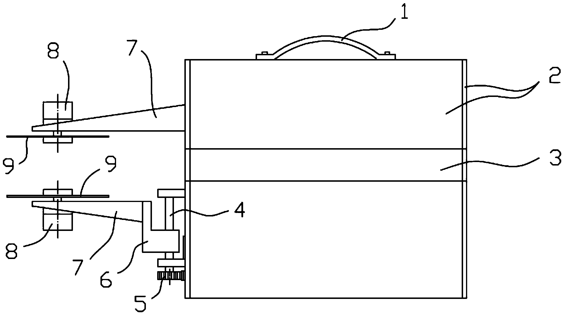
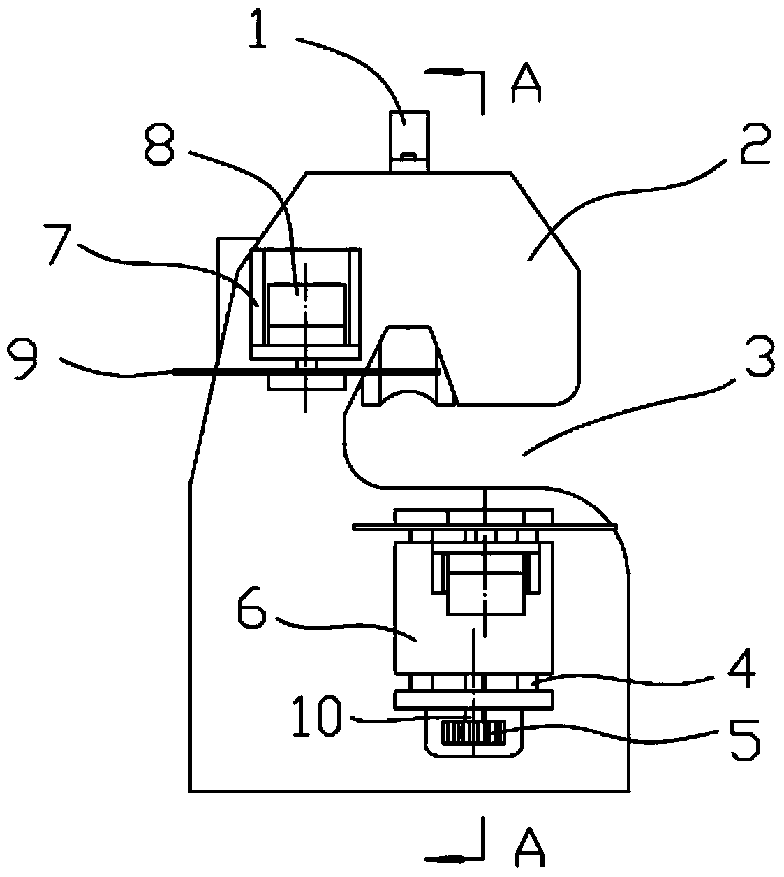
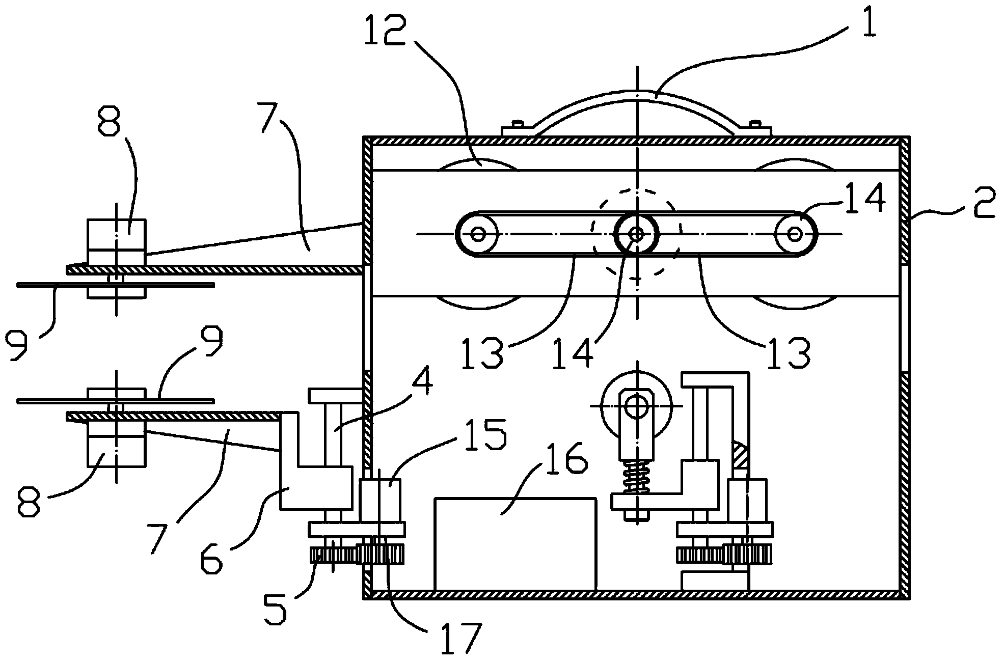
[0029] Such as Figure 1 to Figure 10 As shown, the power transmission line debris removal machine includes a bracket 2, a handle 1 is installed on the top of the bracket 2, and two supporting rollers 12 are rotatably installed on the upper part of the bracket 2, and the two supporting rollers 12 are located in the same plane. A groove suitable for the transmission line is provided on the circumferential surface, and a sprocket 14 is fixed on the roller shaft. Travel motor 29 is installed on the top of support 2, and it is positioned between two support rollers 12, and sprocket wheel 14 is fixed on its output shaft, and this sprocket wheel and the sprocket wheel on support roller 12 axles are connected by chain 13, makes walking The motor 29 can drive the support roller 12 to rotate through the sprocket chain transmission mechanism.

[0030]A knife rest 7 ...


PUM


Abstract

The invention relates to a machine for removing impurities on an electric transmission line. The machine comprises a support, supporting rolling wheels, a walking motor, a cutting motor, a battery and a control circuit, wherein a cutting blade is fixed on the cutting motor, and the control circuit is arranged in the support. One side of the support is provided with a passage for allowing the electric transmission line to go into the support and enabling the electric transmission line to be located below the supporting rolling wheels. A jacking and pressing device is arranged in the support and is composed of a jacking mechanism and a jacking and pressing rolling wheel arranged on the jacking mechanism in a rotatable mode. The jacking and pressing rolling wheel is located below the supporting rolling wheels and can be driven by the jacking mechanism to move perpendicularly, and the jacking and pressing rolling wheel and the supporting rolling wheels are located in the same plane. The machine for removing the impurities on the electric transmission line can steadily and reliably move on the electric transmission line and reliably remove the impurities on the electric transmission line.

Description

technical field [0001] The invention relates to a device used in the electric power industry for cleaning debris on transmission lines. Background technique [0002] It is easy to hang various sundries on the transmission lines used for power transmission, which not only affects the appearance of the city, but also poses certain safety hazards. Since the transmission line, especially the high-voltage transmission line, is relatively high from the ground, it is very difficult for the staff to manually clean up the sundries on the ground. In order to solve the problem of cleaning up debris on transmission lines, engineers and technicians in the electric power industry have designed many devices for cleaning up debris on transmission lines. [0003] The invention patent application with the application number of 2013100363886 discloses a power transmission line debris removal device, which is mainly composed of a "┌┐"-shaped bracket, a movable support plate, a remote control m...

Claims


Application Information

Patent Timeline
IPC IPC(8): H02G1/02B08B1/02
Inventor 王福田
Owner CHONGQING FUTIAN ELECTRIC POWER EQUIP
Why Eureka
Try Eureka