Constant time control method of switching type regulator, control circuit and switching type regulator using control circuit

A constant time, control circuit technology, applied in the direction of adjusting electrical variables, control/regulating systems, instruments, etc., can solve the problems of component damage, output voltage overshoot, slow response to transient changes, etc., to avoid fluctuations, fast transients. Transient response, the effect of improving the transient response speed

Active Publication Date: 2013-12-25
SILERGY SEMICON TECH (HANGZHOU) CO LTD
View PDF4 Cites 14 Cited by
  • Summary
  • Abstract
  • Description
  • Claims
  • Application Information

AI Technical Summary

Problems solved by technology

[0011] Visible, using as Figure 1A The DC-DC converter shown in the constant on-time control scheme responds very slowly to the transient change of the load, and will produce an overshoot of the output voltage, which will cause damage to the components in the circuit

Method used


Image

  • Constant time control method of switching type regulator, control circuit and switching type regulator using control circuit
  • Constant time control method of switching type regulator, control circuit and switching type regulator using control circuit
  • Constant time control method of switching type regulator, control circuit and switching type regulator using control circuit

Examples


Embodiment Construction

[0060] Several preferred embodiments of the present invention will be described in detail below with reference to the accompanying drawings, but the present invention is not limited to these embodiments. The present invention covers any alternatives, modifications, equivalent methods and schemes made on the spirit and scope of the present invention. In order to provide the public with a thorough understanding of the present invention, specific details are set forth in the following preferred embodiments of the present invention, but those skilled in the art can fully understand the present invention without the description of these details.

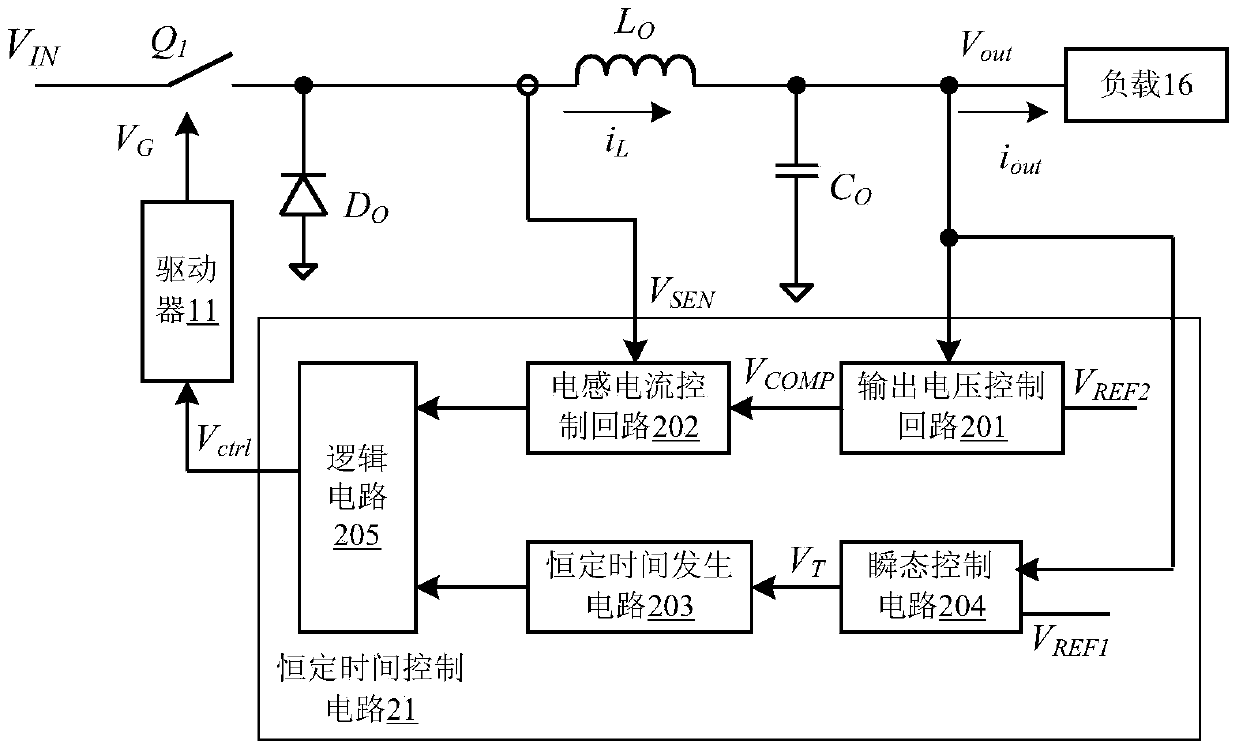
[0061] refer to figure 2 , shows a schematic block diagram of a preferred embodiment of a constant-time control circuit for a switching regulator according to the present invention.

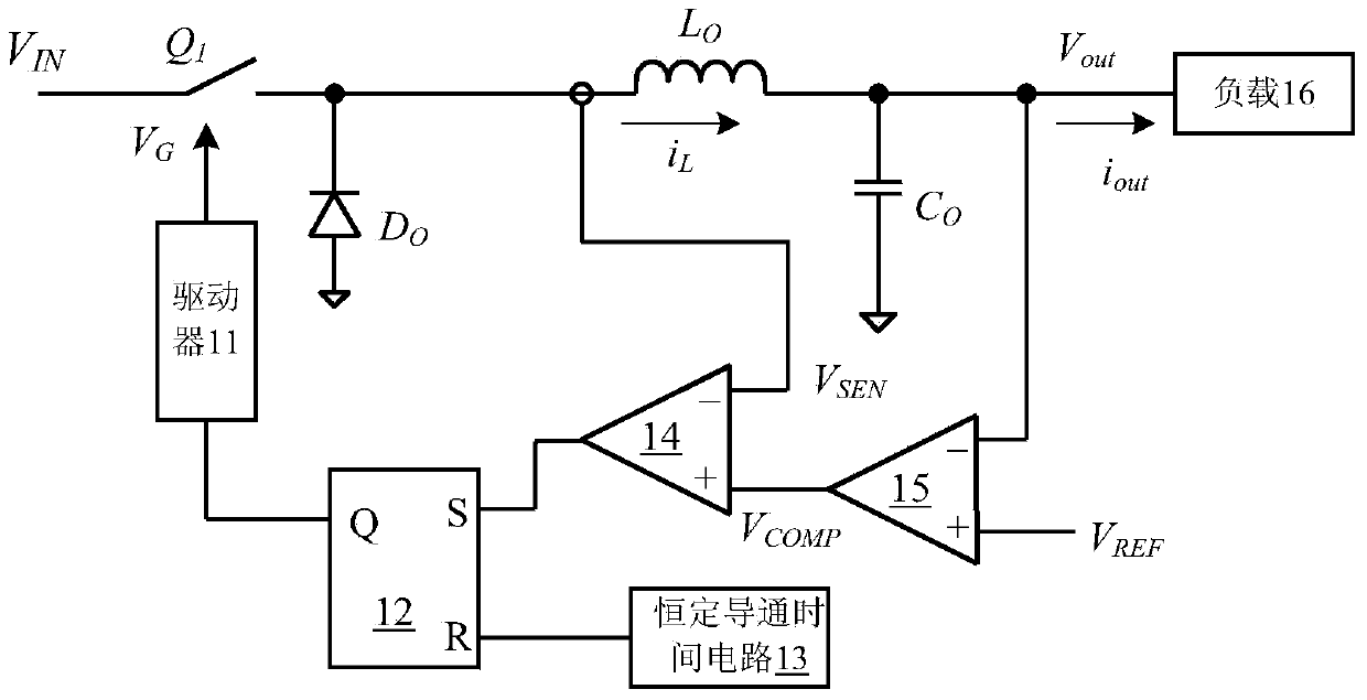
[0062] In this embodiment, the working principle of the constant time control circuit is described by taking a step-down switching regulator as an example...


PUM


Abstract

The invention discloses a constant time control method of a switching type regulator. The constant time control method of the switching type regulator comprises the steps that the output voltage of the output end of the switching type regulator is detected; the current flowing through an inductor of the switching type regulator is detected; the fact that whether step change happens to a load at the output end of the switching type regulator is judged; when step change does not happen to the load at the output end of the switching type regulator, the state of a switching element in the switching type regulator is controlled according to a generated square wave control signal so that the output voltage can be kept basically constant, wherein the square wave control signal comprises a set of pulses with constant time widths; when step change happens to the load at the output end of the switching type regulator, the pulses with the constant time widths are cut off in advance till a next pulse comes. The constant time control method of the switching type regulator has the advantages that fast transient response to the change of the load is achieved, the transient response speed is improved, and major fluctuations of the output voltage are avoided.

Description

[0001] The application date is "September 14, 2011", the application number is "201110289650.9", and the title of the invention is "a constant time control method for a switching regulator, a control circuit and a switching regulator using the same". Divisional application. technical field [0002] The present invention relates to a power supply technology, and more particularly, to a switching regulator using a constant time control scheme. Background technique [0003] The switching power supply is composed of two parts, the power stage circuit and the control circuit. The function of the control circuit is to adjust the turn-on and turn-off time of the switching system in the power stage circuit when the input voltage, internal parameters and external load change, so as to keep the output voltage or output current of the switching power supply constant. Therefore, in the design of the switching power supply, the selection and design of the control method are very importa...

Claims


Application Information

Patent Timeline
Patent Type & Authority Applications(China)
IPC IPC(8): H02M3/00H02M3/10
CPCH02M3/156H02M3/1566H02M3/157
Inventor 陈伟
Owner SILERGY SEMICON TECH (HANGZHOU) CO LTD
Why Eureka
Try Eureka