
Digital-to-analog converter with sectional capacitor array structure

A digital-to-analog converter, array structure technology, applied in digital-to-analog converter, analog-to-digital conversion, code conversion and other directions, can solve the problems of gain error, deterioration, mismatch, etc., to improve NDL and IDL, eliminate capacitance loss. Matching and eliminating the effect of gain error

Active Publication Date: 2013-12-25
SHENZHEN GOODIX TECH CO LTD
View PDF4 Cites 42 Cited by
  • Summary
  • Abstract
  • Description
  • Claims
  • Application Information

AI Technical Summary

Problems solved by technology

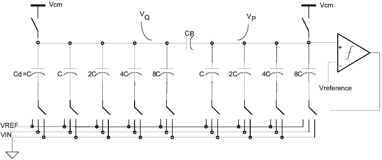
In order to ensure that the equivalent capacitance of the sub-array on the left side of the bridge capacitor is equal to the lowest capacitance value in the right sub-array during the capacitor redistribution process, the bridge capacitor C B It can only be a non-integer multiple of the unit capacitance C. Obviously, this will introduce a serious mismatch problem and may cause gain errors
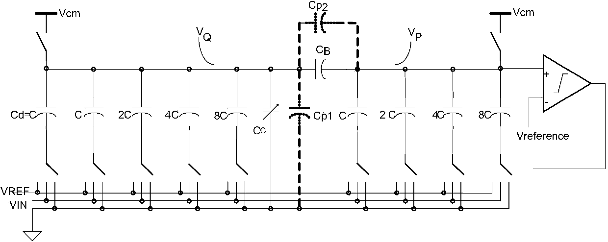
[0004] In addition, there is a more serious problem in the above structure, due to the bridge capacitance C B Special binary capacitance design of the left sub-array, node V Q and node V Q and V P There is a non-negligible parasitic capacitance between them, and its size is sensitive to the process implementation (metal routing path, selected level), which will be in C B A large mismatch is introduced between the left and right capacitor sub-arrays, and eventually causes the deterioration of DNL (Differential Nonlinearity, differential nonlinearity) and INL (Integral nonlinearity, integral nonlinearity)

Method used


Image

  • Digital-to-analog converter with sectional capacitor array structure
  • Digital-to-analog converter with sectional capacitor array structure
  • Digital-to-analog converter with sectional capacitor array structure

Examples


Embodiment Construction

[0020] In order to make the technical problems, technical solutions and beneficial effects to be solved by the present invention clearer and clearer, the present invention will be further described in detail below in conjunction with the accompanying drawings and embodiments. It should be understood that the specific embodiments described here are only used to explain the present invention, not to limit the present invention.

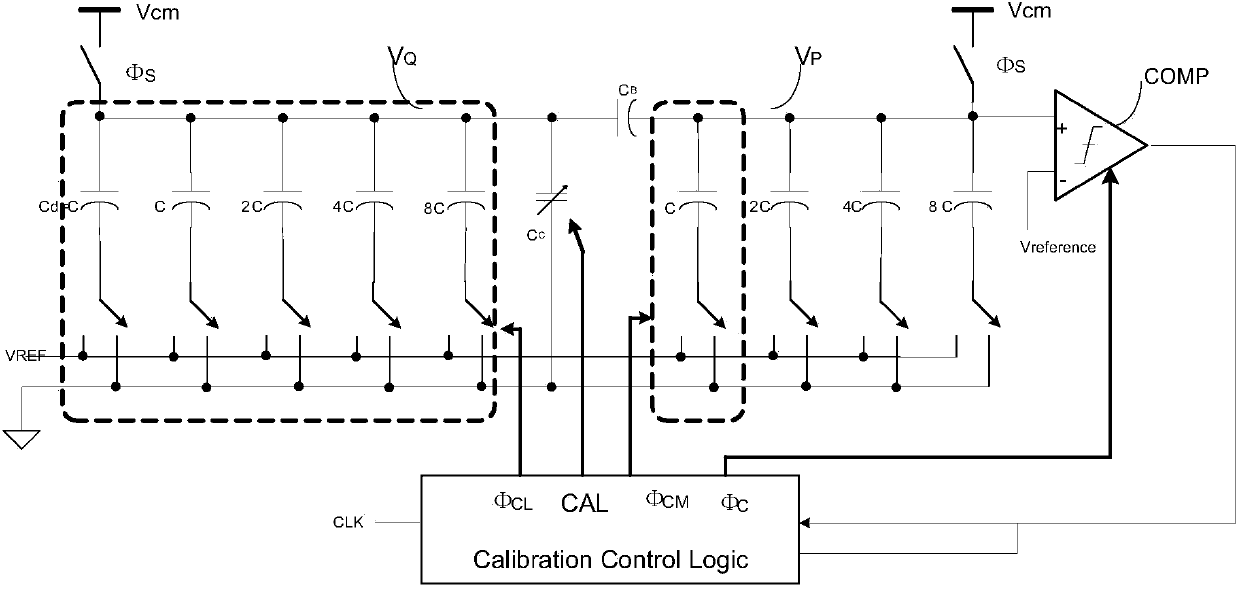
[0021] Such as figure 2 Schematic diagram of the DAC correction principle of the segmented charge redistribution capacitor array provided by the embodiment of the present invention, in the figure:

[0022] Capacitance C B For bridging capacitors, connect the left and right capacitor sub-arrays respectively. Wherein, the subarray on the left corresponds to quantization bits with lower weights, and the subarray on the right corresponds to quantization bits with higher conversion weights. C d is the matching capacitance of the minimum weight bit capac...


PUM


Abstract

The invention discloses a digital-to-analog converter with a sectional capacitor array structure. The digital-to-analog converter comprises at least two capacitor subarrays and at least one bridging capacitor CB, wherein each bridging capacitor CB is connected with two qualification-bit capacitor subarrays with adjacent weights; the low-level capacitor subarray of each bridging capacitor CB is connected with a compensating capacitor CC with an adjustable capacitance value in parallel; the compensating capacitor CC enables the capacitance value of an equivalent capacitor in the compensated low-level capacitor subarray to be equal to that of the lowest-level capacitor in the high-level capacitor subarray connected with the bridging capacitor CB. The digital-to-analog converter disclosed by the invention has the advantages that by adoption of the embodiment, the compensating capacitor CC with the adjustable capacitance value is introduced, and the capacitance value of the compensating capacitor CC is set according to the bridging capacitor CB and parasitic capacitors at common nodes of the capacitor subarrays at the two ends, so that the capacitor mismatching among the capacitor subarrays is eliminated, the linearity is further improved while gain error is eliminated, and DNL (Differential Non Linearity) and INL (Integral Non Linearity) of a successive approximation ADC (Analog to Digital Converter) are finally improved.

Description

technical field [0001] The invention belongs to the field of electronic circuits, in particular to a digital-to-analog converter with segmented capacitor array structure. Background technique [0002] The successive approximation ADC (Analog to Digital Converter, analog-to-digital converter) based on the principle of charge redistribution has the advantage of lower power consumption, but the number of capacitors significantly increased by the number of digits with binary weights, and the resulting large The problem of input capacitive load makes its application somewhat limited. [0003] In order to solve this problem, the approach in related technologies is to divide the entire capacitor array into segments and connect them with one (two segments) or multiple (multi-segments) bridging capacitors. Such as figure 1 Shown is an 8-bit charge redistribution DAC (Digital to Analog Converter), capacitor C B For bridging capacitors, connect the left and right capacitor sub-array...

Claims


Application Information

Patent Timeline
IPC IPC(8): H03M1/66
CPCH03M1/1014H03M1/468
Inventor 陈松涛
Owner SHENZHEN GOODIX TECH CO LTD
Learn More