
Ultrasound diagnostic device

A diagnostic device, ultrasonic technology, applied in the direction of acoustic wave diagnosis, infrasonic wave diagnosis, ultrasonic/sonic wave/infrasonic wave diagnosis, etc., which can solve the problems of a large amount of labor and complicated operations for users

Active Publication Date: 2013-12-25
HITACHI HEALTHCARE MFG LTD
View PDF5 Cites 4 Cited by
  • Summary
  • Abstract
  • Description
  • Claims
  • Application Information

AI Technical Summary

Problems solved by technology

[0004] However, when the position of the cut plane is set for each follicle including the major axis or the minor axis, if the user manually implements the setting, the user will be forced to perform complicated operations.
In particular, since a plurality of follicles are densely packed in a living body, manually setting a cut plane for each of the plurality of follicles requires a lot of labor.

Method used


Image

  • Ultrasound diagnostic device
  • Ultrasound diagnostic device
  • Ultrasound diagnostic device

Examples


Embodiment Construction

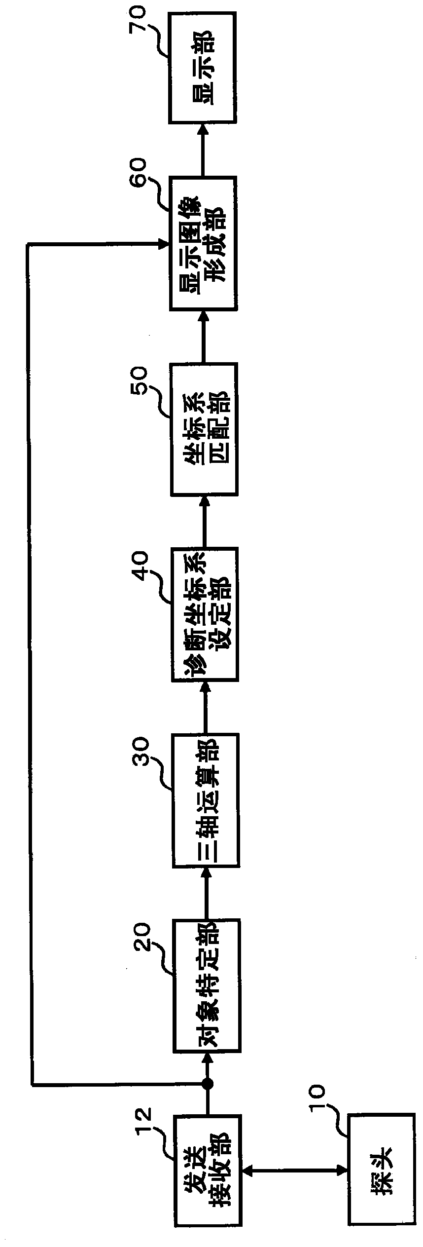
[0029] figure 1 It is a diagram showing the overall configuration of an ultrasonic diagnostic apparatus preferable for carrying out the present invention. The probe 10 is an ultrasonic probe that transmits and receives ultrasonic waves to and from an area including a diagnostic object. The probe 10 includes a plurality of vibrating elements for transmitting and receiving ultrasonic waves, and the plurality of vibrating elements are subjected to transmission control by the transmitting and receiving unit 12 to form a transmission signal beam. In addition, a plurality of vibration elements receive ultrasonic waves obtained from an area including the diagnostic object, thereby outputting the obtained signals to the transmitting and receiving unit 12, so that the transmitting and receiving unit 12 forms a received signal beam and follows the received signal beam. Collect echo data.

[0030] The probe 10 is preferably a three-dimensional probe, and the three-dimensional probe sca...


PUM


Abstract

The invention relates to an ultrasound diagnostic device. A diagnostic coordinate system specified by a first axis through a third axis is a coordinate system based on a major axis and a minor axis of a follicle F, and the starting point is at the position of the center of gravity of the follicle (F). The display coordinate system is an XYZ coordinate system. The diagnostic coordinate system is moved in parallel to the display coordinate system from (A) until the starting points are aligned at (B). The diagnostic coordinate system is then rotated until the first axis of the diagnostic coordinate system corresponding to the major axis of the follicle F overlaps the x-axis where the angle with the first axis is smallest, at (C). Additionally, the diagnostic coordinate system is rotated until the second axis of the diagnostic coordinate system corresponding to the minor axis of the follicle F overlaps the z-axis where the angle with the second axis is smallest, at (D). A tomographic image of the follicle F is formed by an image in a plane that includes the z-axis and the x-axis, an image in a plane that includes the y-axis and the z-axis, and an image in a plane that includes the x-axis and the y-axis.

Description

technical field [0001] The present invention relates to an ultrasonic diagnostic device, in particular to a technique for forming a display image of a diagnostic object. Background technique [0002] Conventionally, there is known a technique for displaying ultrasonic images of tissues or the like with display images suitable for diagnosis, and the display images are varied according to the types of tissues or the like and diagnosis contents. Furthermore, as the tissues and the like, a plurality of follicles in a living body are also targeted for ultrasonic diagnosis. [0003] Each follicle is often observed to have a shape approximately close to an ellipse. Therefore, for example, the long axis along the long side direction of each follicle or the short axis orthogonal thereto is set as benchmark. Accordingly, for example, when obtaining ultrasonic image data three-dimensionally and displaying a sectional image of each follicle, there are not many users who desire to obta...

Claims


Application Information

Patent Timeline
Patent Type & Authority Applications(China)
IPC IPC(8): A61B8/00
CPCA61B8/466G06T19/20G06T2210/41G06T2219/028G06T2219/2016G06T7/60G06T2207/10136G06T2207/20036G06T2207/30004G01S7/52073G01S7/52074A61B8/483G06T7/73G06T7/11G06T7/155A61B8/13A61B8/5207
Inventor 永瀬优子松下典义
Owner HITACHI HEALTHCARE MFG LTD
Learn More