Ankle joint rehabilitation device

A rehabilitation device and ankle joint technology, applied in passive exercise equipment, physiotherapy and other directions, can solve the problems of singular working space of parallel mechanism, non-overlapping rotation centers, and non-overlapping rotation centers, so as to avoid additional interference and avoid Energy loss, the effect of eliminating singular poses

Inactive Publication Date: 2014-01-01
BEIJING JIAOTONG UNIV
View PDF5 Cites 52 Cited by
  • Summary
  • Abstract
  • Description
  • Claims
  • Application Information

AI Technical Summary

Problems solved by technology

However, the above two mechanisms have the same problem, that is, the rotation centers of the mechanism and the ankle joint do not coincide with each other, causing the lower leg to move with the ankle joint, which reduces the comfort of the patient during training
In order to solve the singular problem in the working space of the parallel mechanism, Saglia et al. from King’s College London proposed a two-degree-of-freedom 3-SPS / U redundantly driven ankle joint rehabilitation mechanism, but there is also the problem that the centers of rotation do not coincide
In addition, Tsoi of the University of Auckland also proposed a three-degree-of-freedom redundant drive 4-UPS / S ankle joint rehabilitation robot. Although it can achieve rehabilitation training with the ankle joint as the center of rotation, the lower limbs of the patient will be affected by other directions. force, affecting the recovery effect

Method used


Image

  • Ankle joint rehabilitation device
  • Ankle joint rehabilitation device
  • Ankle joint rehabilitation device

Examples


Embodiment 1

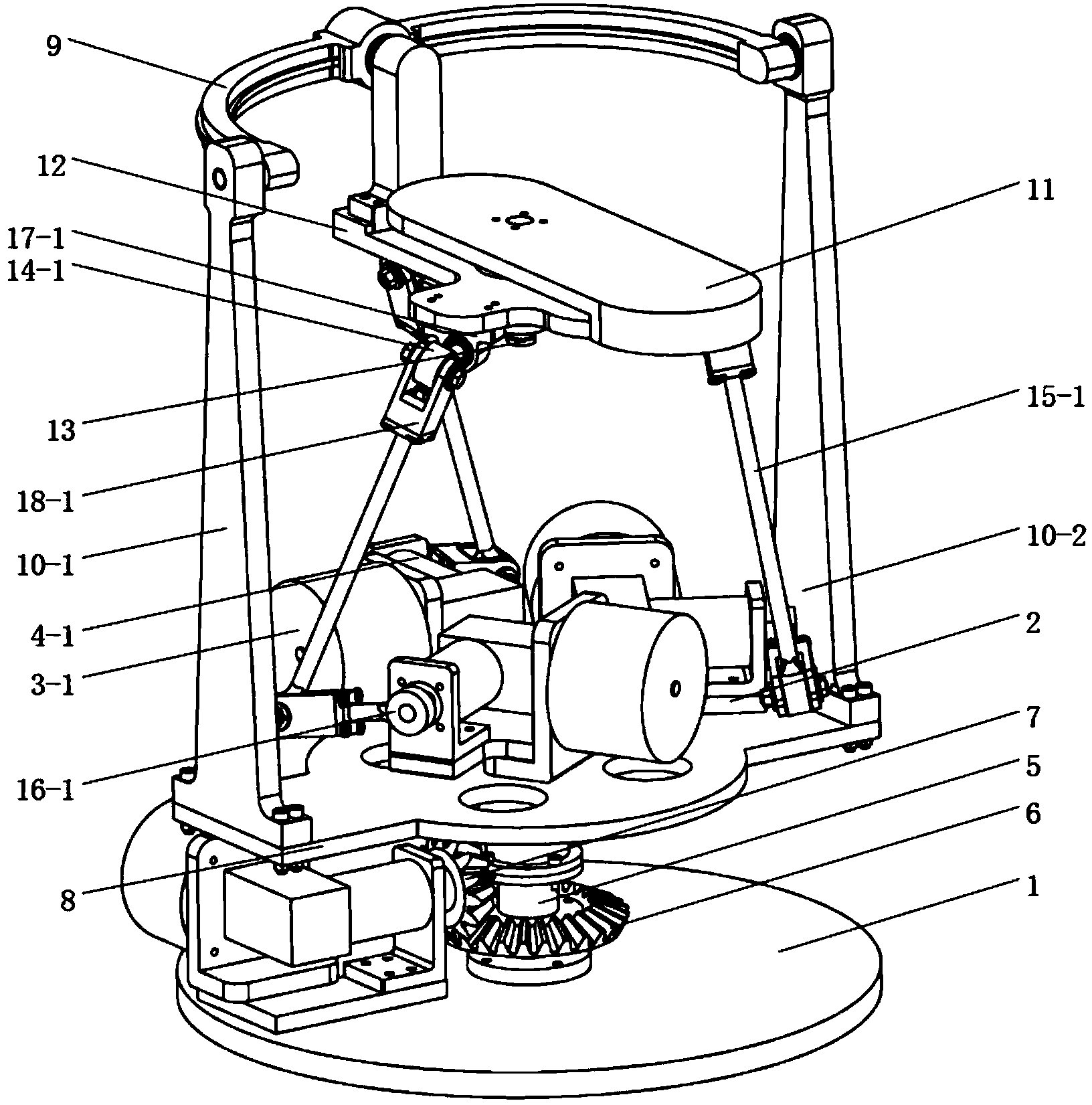
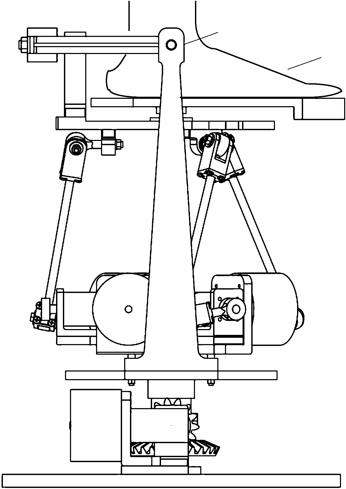
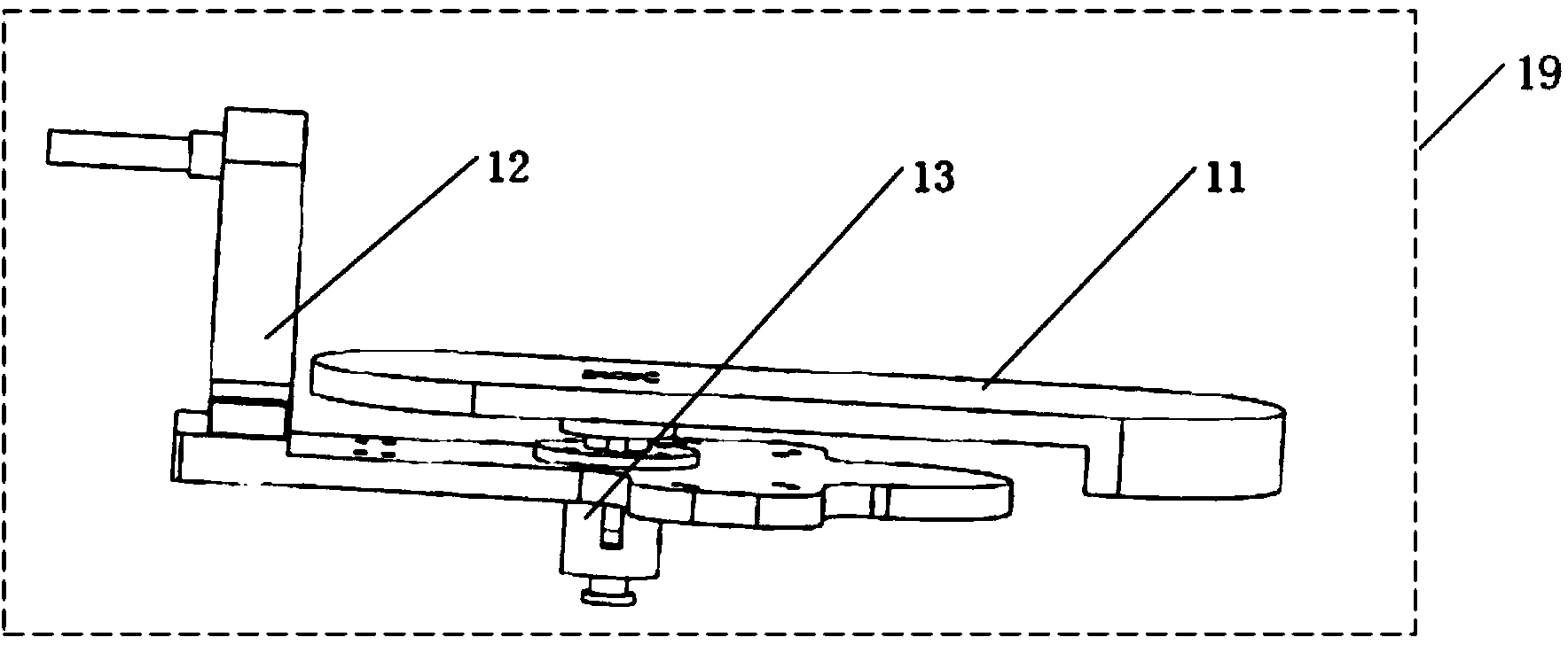
[0029] Such as Figure 1-Figure 9 As shown, an ankle joint rehabilitation device includes a base, a moving platform 19 , an active branch chain 20 and a constraint branch chain 21 . The base includes a base 1 and a support platform 2, the support platform 2 is fixed on the base 1 by a support rod 1-1; the base 1 is fixed with a fourth motor 3-4, and the support platform 2 is fixed on the base 1. A first motor 3-1, a second motor 3-2 and a third motor 3-3 are fixed. A first right-angle reducer 4-1 is connected to the first motor 3-1, a second right-angle reducer 4-2 is connected to the second motor 3-2, and a second right-angle reducer 4-2 is connected to the third motor 3-3. There is a third right-angle reducer 4-3, and a fourth right-angle reducer 4-4 is connected to the fourth motor 3-4.

[0030] Figure 8It is a schematic diagram of the constraint branch chain 21, the constraint branch chain 21 is rotatably arranged on the base, and the constraint branch chain 21 include...

Embodiment 2

[0044] The structure of embodiment 2 is the same as that of embodiment 1, the difference is that the fourth motor 3-4 realizes self-locking through methods such as brakes, that is, the fourth right-angle reducer 4-4 and the bevel pinion gear 7 lose power. Rotate again, then the large bevel gear 6 no longer rotates, and the bearing platform 8 and the base have no relative rotation, which limits the degree of freedom that the restraint branch chain 21 rotates around the Z axis; at this time, the first motor 3-1, the second Two motors 3-2 and the third motor 3-3 are driven by active branch chain 20, and this device can only realize as Figure 8 The rotation of degrees of freedom in the two directions of the X-axis and Y-axis shown, that is, the dorsiflexion / plantarflexion of the ankle joint, and the two directions of varus / valgus, can selectively perform rehabilitation training on the ankle joint.


PUM


Abstract

An ankle joint rehabilitation device comprises a base assembly, a moving platform, a driving branch and a limit branch. The base assembly comprises a base and a support platform. The support platform is fixed on the base through a support bar. The limit branch is rotatably disposed on the base and comprises a bearing platform, a left support link, a right support link and an arc link. The bearing platform is disposed on the support bar in a sleeving manner. The driving branch comprises a first driving branch, a second driving branch and a third driving branch. The first, second, and third driving branches are parallel RUS branches. The limit branch and the moving platform allow for three-directional rotation; rotation centers can be overlapped; axes of the limit branch are mutually orthogonal, so that the device features partial decoupling of motion.

Description

technical field [0001] The invention relates to the field of rehabilitation medical equipment, in particular to a redundantly driven ankle joint rehabilitation device for performing rehabilitation training on patients after ankle joint trauma. Background technique [0002] The ankle joint is one of the main load-bearing structures of the human body, bearing all the weight of the body when the human body stands and walks. Especially when running, jumping and carrying weight on the body, the ankle joint bears huge loads and impacts, so joint injuries or sprains are the most common in daily life. After the ankle joint is injured, if it is not properly treated and recovered, it will form traumatic arthritis, which will cause long-term ankle pain, lameness, dysfunction and other symptoms, which will affect work and life. Relevant clinical medicine has proved that correct and scientific ankle joint rehabilitation training plays a very important role in the recovery and improvemen...

Claims


Application Information

Patent Timeline
Patent Type & Authority Applications(China)
IPC IPC(8): A61H1/02
Inventor 汪从哲方跃法禹润田郭盛
Owner BEIJING JIAOTONG UNIV
Why Eureka
Try Eureka