Photovoltaic support main shaft structure and photovoltaic tracking support system comprising same

A photovoltaic support and spindle technology, applied in the support structure of photovoltaic modules, photovoltaic modules, photovoltaic power generation, etc., can solve the problems of increased hoop cost, low installation efficiency, and cumbersome installation, so as to save costs, improve assembly efficiency, and speed up The effect of installation speed

Pending Publication Date: 2021-07-23
江苏曦日新能源科技有限公司
View PDF1 Cites 0 Cited by
  • Summary
  • Abstract
  • Description
  • Claims
  • Application Information

AI Technical Summary

Problems solved by technology

However, this photovoltaic spindle connection device has disadvantages. First, the connection between each unit bushing is clamped by an outsourcing hoop, which is cumbersome to install structurally and increases the cost of the hoop; second, it cannot be quickly installed. Spindle to assemble, resulting in inefficient installation

Method used


Image

  • Photovoltaic support main shaft structure and photovoltaic tracking support system comprising same
  • Photovoltaic support main shaft structure and photovoltaic tracking support system comprising same
  • Photovoltaic support main shaft structure and photovoltaic tracking support system comprising same

Examples


Embodiment 1

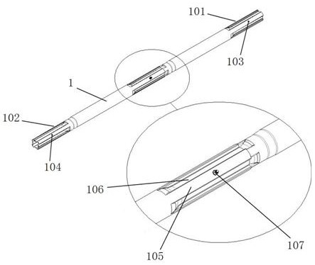
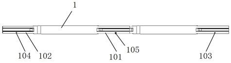
[0031] see Figure 1-6 As shown, this embodiment is a main shaft structure of a photovoltaic support, including a main shaft. There is a shrink tube end 102 embedded in it. The respective ports of the outer shrink tube end 101 and the inner shrink tube end 102 include axial protrusions 105 and axial recesses 106 alternately distributed along the circumferential direction, and the axial recesses 106 of the outer shrink tube end 101 and the inner shrink tube end 102 and The axial convex part 105 is radially positioned by means of loose fit, and the lock of the main shaft is achieved through the fit.

[0032] In this embodiment, the outer shrink tube end 101 is provided with an outer positioning hole 103, and the inner shrink tube end 102 is correspondingly provided with an inner positioning hole 104. The fasteners 107 in the positioning holes 103 and the inner positioning holes 104 are fixed, and the fasteners can be tightened nuts.

[0033] In this embodiment, the outer posi...

Embodiment 2

[0038] The structure and application of this embodiment are basically the same as those of Embodiment 1, the difference is that the outer positioning hole 103 is located on the axial recess 106 of the outer shrink tube end 101, and the inner positioning hole 104 is located on the inner shrink tube On the axial recess 106 of the end 102.

Embodiment 3

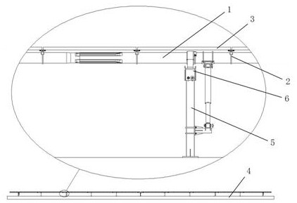
[0040] This embodiment is a photovoltaic tracking support system, which includes a base 4, a column 5, a first purlin assembly 6, a second purlin assembly 2, a photovoltaic module panel 3 and the photovoltaic support as described in the first embodiment Spindle structure. The main shaft 1 of the photovoltaic support main shaft structure is fixedly supported by the photovoltaic module panel 3 through the second purlin assembly 2 , and the base 4 provides rotational support for the main shaft through the column 5 and the first purlin assembly 6 .


PUM


Abstract

The invention discloses a photovoltaic support main shaft structure and a photovoltaic tracking support system comprising the same. The photovoltaic support main shaft structure comprises a main shaft, wherein the main shaft is a combined shaft formed by combining a plurality of unit shaft sleeves, one end of each unit shaft sleeve is provided with a sleeving contracted pipe end, the other end of each unit shaft sleeve is provided with an embedded contracted pipe end, a port of the sleeving contracted pipe end and a port of the embedded contracted pipe end comprise axial convex parts and axial concave parts which are alternately distributed in the circumferential direction respectively, the axial concave parts and the axial convex parts of the sleeving contracted pipe end and the embedded contracted pipe end are radially positioned in a clearance fit mode, and locking of the main shaft is achieved in a matched mode. According to the multi-point clamping and sleeving and embedding main shaft, the inner side of the port of the main shaft is in the shape of a polygon which is convex outwards and concave inwards, after clamping, the main shaft can be locked, the torque can be adjusted, sliding at the connecting position of the main shaft is effectively avoided, and it is guaranteed that the axes of unit shaft sleeves coincide with one another.

Description

technical field [0001] The invention relates to the technical field of photovoltaic supports, in particular to a photovoltaic support main shaft structure and a photovoltaic tracking support system comprising the same. Background technique [0002] Solar photovoltaic power generation is a technology that accepts incident sunlight by using an array formed by a subsystem of solar photovoltaic modules, converts light energy into electrical energy through photovoltaic conversion, and collects the generated electrical energy for use. Solar photovoltaic systems usually use bracket structures to install solar photovoltaic arrays. Photovoltaic tracking support solutions are generally divided into single-row modules with single-axis independent drive, single-row modules with multi-axis linkage drive, multi-row modules with single-axis independent drive, and multi-row modules with multi-axis linkage drive. The single-axis tracking support system has a rotatable main shaft part, and o...

Claims


Application Information

Patent Timeline
Patent Type & Authority Applications(China)
IPC IPC(8): F16C3/02F24S30/425H02S20/00H02S20/30H02S20/32
CPCF16C3/023F24S30/425H02S20/00H02S20/30H02S20/32Y02E10/47Y02E10/50
Inventor 谢入金
Owner 江苏曦日新能源科技有限公司
Why Eureka
Try Eureka