Supercharge Your Innovation With Domain-Expert AI Agents!

Basket Mill

A basket grinder and basket body technology, applied in the grinder field, can solve problems such as easy wear and blockage of the screen, affecting grinding efficiency and service life, and achieve the effects of improving production efficiency, not being easily deformed by pressure, and having a long service life

Inactive Publication Date: 2015-12-09
FARFLY ENERGY TECH
View PDF13 Cites 0 Cited by
  • Summary
  • Abstract
  • Description
  • Claims
  • Application Information

AI Technical Summary

Problems solved by technology

[0004] In order to overcome the disadvantages that the screen in the basket grinder in the prior art is easy to wear and block, which seriously affects the grinding efficiency and service life, the invention provides a basket grinder with a screen that is not easy to wear and block and has high grinding efficiency machine

Method used


Image

  • Basket Mill
  • Basket Mill
  • Basket Mill

Examples


Embodiment 1

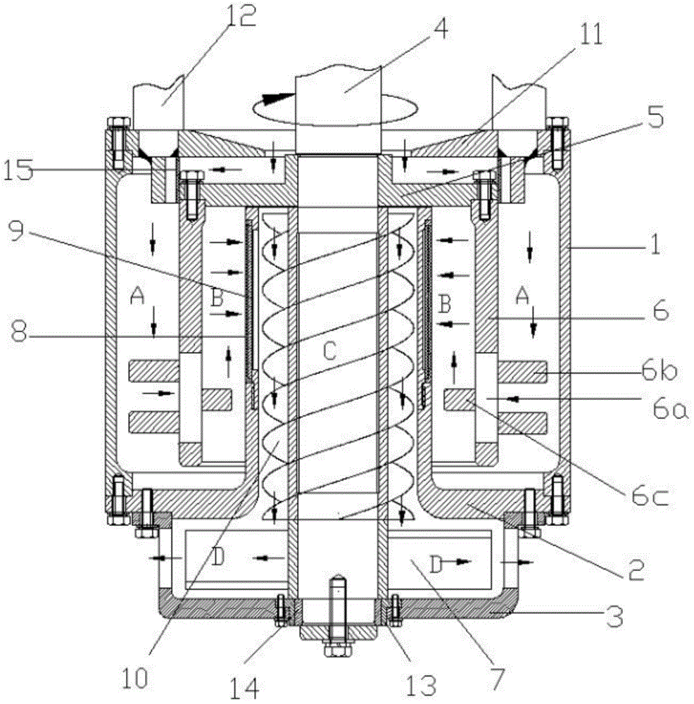
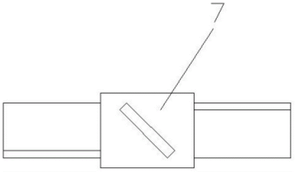
[0025] Embodiment 1: as figure 1 , image 3 with Figure 4 A basket grinder shown includes a grinding basket body 1, a grinding basket bottom 2 connected to the bottom of the grinding basket body, a bracket 3 supporting the grinding basket bottom, and a main shaft 4 driven by a motor, and the main shaft 4 runs through the grinding up and down in sequence Basket body 1, grinding basket bottom 2 and bracket 3, the grinding basket body 1 is provided with a centrifugal impeller 5 and a drum 6 in sequence from top to bottom, the centrifugal impeller 5 is fixed on the top of the drum 6, and the blades of the centrifugal impeller 5 It is a centrifugal back-curved blade, and the height of the blade decreases gradually along the radial direction; the drum 6 is fixed on the main shaft 4, and the lower end of the main shaft 4 is also fixed with a stirring device 7, which is arranged in the support 3, and the drum An annular first grinding passage is formed between the outer wall of 6 a...

Embodiment 2

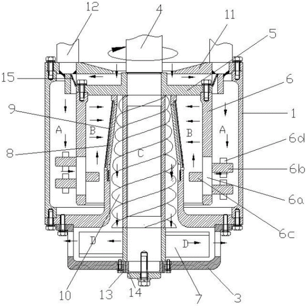
[0026] Embodiment 2: as figure 2 image 3 Figure 4 A basket grinder is shown, comprising a grinding basket body 1, a grinding basket bottom 2 connected to the bottom of the grinding basket body, a bracket 3 supporting the bottom of the grinding basket and a main shaft 4 driven by a motor, the main shaft 4 runs through the grinding basket up and down sequentially Body 1, grinding basket bottom 2 and bracket 3, the grinding basket body 1 is provided with a centrifugal impeller 5 and a drum 6 sequentially from top to bottom, the centrifugal impeller 5 is fixed on the top of the drum 6, and the blades of the centrifugal impeller 5 are Centrifugal back-curved blades, the height of the blades gradually decreases along the radial direction; the drum 6 is fixed on the main shaft 4, and the lower end of the main shaft 4 is also fixed with a stirring device 7, which is arranged in the bracket 3, and the drum 6 An annular first grinding channel is formed between the outer wall of the...


PUM


Abstract

The invention discloses a basket mill. The basket mill comprises a milling basket body, a milling basket bottom connected with the bottom of the milling basket body, a bracket for supporting the milling basket bottom and a spindle, wherein the spindle sequentially penetrates through the milling basket body, the milling basket bottom and the bracket vertically, a centrifugal impeller and a drum are sequentially arranged in the milling basket body from top to bottom, a stirring device is also fixed at the lower end of the spindle, a first milling channel is formed between the drum and the milling basket body, a milling inlet channel is formed above the centrifugal impeller, a first screen is arranged at the upper end of an inner ring of the milling basket bottom, a second milling channel is formed between the first screen and the drum, the first milling channel is communicated with the second milling channel, a third milling channel is formed between the first screen and the spindle, a part of the second milling channel passing through the first screen is communicated with the third milling channel, and a milling output channel communicated with the lower end of the third milling channel is formed in the side surface of the bracket. Therefore, the basket mill has the beneficial effects that the screen is not easy to wear or jam, and the milling efficiency is high.

Description

technical field [0001] The invention relates to a grinder, in particular to a basket grinder. Background technique [0002] Basket mills currently used for wet crushing are composed of a circular basket, a screen for separating materials and grinding media, a stirring device in the basket, and a suction impeller on the main shaft of the stirring device. The basket contains a certain amount of grinding beads. When working, the basket is vertically immersed in the container, and through the rotation of the stirring device, the grinding beads in the basket and the material are repeatedly collided and sheared to achieve the dispersion and refinement of the material. In order to make the material circulate up and down in the container, a suction impeller is arranged on the upper part of the grinding basket. However, since the screen is located at the bottom of the grinding basket, the grinding media will frequently rub against the screen during use, resulting in wear of the scre...

Claims


Application Information

Patent Timeline
Patent Type & Authority Patents(China)
IPC IPC(8): B02C17/10B02C17/18
Inventor 袁建忠张建国蒋为华
Owner FARFLY ENERGY TECH
Features
  • R&D
  • Intellectual Property
  • Life Sciences
  • Materials
  • Tech Scout
  • Unparalleled Data Quality
  • Higher Quality Content
  • 60% Fewer Hallucinations
Learn More