Supercharge Your Innovation With Domain-Expert AI Agents!

Shearing device for truss production line

A shearing device and production line technology, applied in the direction of shearing devices, shearing equipment, metal processing equipment, etc., can solve the problems of large impact on the power grid, affecting the straightness of the truss, uneven truss cuts, etc., to achieve easy control and adjustment , the effect of simple structure

Inactive Publication Date: 2014-01-01
TJK MACHINERY TIANJIN
View PDF10 Cites 6 Cited by
  • Summary
  • Abstract
  • Description
  • Claims
  • Application Information

AI Technical Summary

Problems solved by technology

[0002] At present, the shearing device for cutting the truss in the truss production line includes three structural modes: the first is the hydraulic horizontal direct push shearing mode; the second is the mechanically driven eccentric slider swing shearing mode; the third is the hydraulic alternating The shearing method of shearing, the above three structural methods have the following defects: the first one adopts the hydraulic horizontal direct push shearing structure, the truss after shearing has serious overall bending at the cutting head of the truss, which affects the straightness of the truss
The second type adopts a mechanically driven eccentric slider swinging shear structure. Due to the intermittent start and stop of mechanical shearing, the vibration of the truss is large, and the cuts of the truss are uneven after shearing; in addition, the brake in the shearing device is easily damaged, and the power of the motor is large. big impact
The third is the shearing method of hydraulic cross-shearing. The hydraulic cross-shearing cuts out the wide mouth of the inner side of the truss.

Method used


Image

  • Shearing device for truss production line
  • Shearing device for truss production line
  • Shearing device for truss production line

Examples


Embodiment Construction

[0018] Embodiments of the present invention will be further described below in conjunction with the accompanying drawings.

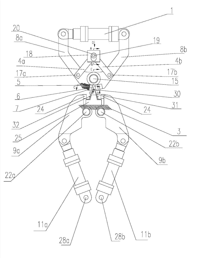
[0019] The present invention provides a shearing device for a truss production line, the shearing device comprises: an upper shearing device for shearing the upper spiral 30 of a truss 31, and a lower shearing device for shearing two lower spirals 32 of a truss 31 , respectively drive the driving device of the upper shearing device and the lower shearing device.

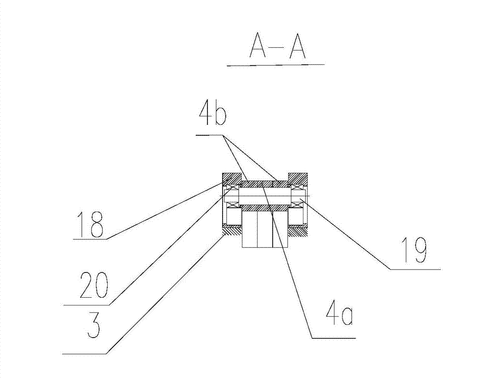
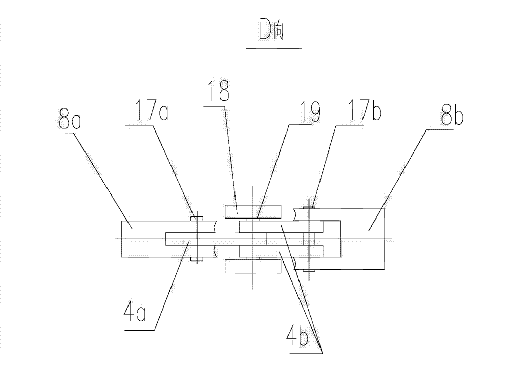
[0020] The upper shearing device is arranged above the upper spiral 30, and its structure includes: an upper shear shaft 15 arranged above the upper spiral 30 and fixed on the frame 3, on which the upper shear shaft 15 is hinged a mirror-symmetrical first One upper shearing arm 8a and the second upper shearing arm 8b, one end of the same side on the first upper shearing arm 8a and the second upper shearing arm 8b is respectively equipped with a pair of identical structure and positioned at the ...


PUM


Abstract

The invention discloses a shearing device for a truss production line. The shearing device comprises an upper shearing device and a lower shearing device. The upper shearing device includes that a pair of upper scissors is installed at one end of a first upper shearing arm and one end of a second upper shearing arm which are hinged to an upper shearing shaft, and the other end of the first upper shearing arm and the other end of the second upper shearing arm are hinged to two piston rods of a double-piston cylinder respectively. The lower shearing device includes that lower scissors are installed at one end of a first lower shearing arm and one end of a second lower shearing arm which are installed on two lower shearing shafts respectively, and the other ends of the first lower shearing arm and the second lower shearing arm are hinged to piston rods of a first cylinder and a second cylinder respectively. Lower fixed scissors are arranged between two lower rotating ribs and fixed on a frame. The device has the advantages of adopting a lever shearing structure to shear upper rotating ribs and the lower rotating ribs step by step, utilizing a simple mechanical structure to prevent collision of the upper scissors and being simple in structure and convenient to adjust and control.

Description

technical field [0001] The invention relates to a truss production line, in particular to a shearing device of the truss production line. Background technique [0002] At present, the shearing device for cutting the truss in the truss production line includes three structural modes: the first is the hydraulic horizontal direct push shearing mode; the second is the mechanically driven eccentric slider swing shearing mode; the third is the hydraulic alternating The shearing method of shearing, the above three structural methods have the following defects: the first one adopts the hydraulic horizontal direct push shearing structure, the truss after shearing has serious overall bending at the cutting head of the truss, which affects the straightness of the truss. The second type adopts a mechanically driven eccentric slider swinging shear structure. Due to the intermittent start and stop of mechanical shearing, the vibration of the truss is large, and the cuts of the truss are u...

Claims


Application Information

Patent Timeline
Patent Type & Authority Applications(China)
IPC IPC(8): B21F11/00B23D17/02B23D17/06
Inventor 陈振东
Owner TJK MACHINERY TIANJIN
Features
  • R&D
  • Intellectual Property
  • Life Sciences
  • Materials
  • Tech Scout
  • Unparalleled Data Quality
  • Higher Quality Content
  • 60% Fewer Hallucinations
Learn More