
Multi-freedom-degree manipulator fixture

A technology of manipulator and degrees of freedom, applied in the direction of manipulator, program-controlled manipulator, chuck, etc., can solve the problems of complex mechanism, difficulty in adjusting workpiece clamping force, and difficulty in adapting to workpieces of various sizes, and achieves safe and convenient operation and strong versatility. , the effect of simple structure

Active Publication Date: 2014-01-01
CRRC QINGDAO SIFANG CO LTD
View PDF7 Cites 17 Cited by
  • Summary
  • Abstract
  • Description
  • Claims
  • Application Information

AI Technical Summary

Problems solved by technology

[0002] Most of the existing power-assisted manipulator claw clamping and clamping mechanisms are special-purpose clamping fixtures with low versatility, and generally have the following problems: 1. The mechanism has a small degree of freedom and is difficult to adapt to the needs of workpieces of various sizes
2. It is difficult to overturn the workpiece. Even if it is overturned, it is difficult to accurately locate the position of the workpiece. As a result, after the workpiece is overturned, it needs to be repositioned and then clamped. The clamping efficiency is not high, and it is time-consuming and difficult to operate.
3. It is difficult to adjust the clamping force on the workpiece. Different workpieces have different quality requirements on the surface of the workpiece and the rigidity of the workpiece. Different requirements are put forward for the clamping force of the manipulator fixture. The existing manipulator generally has a fixed clamping force. , even if the change of clamping force is realized, the mechanism will be complicated, so it is difficult to meet the actual production requirements

Method used


Image

  • Multi-freedom-degree manipulator fixture
  • Multi-freedom-degree manipulator fixture

Examples


Embodiment Construction

[0019] The present invention will be further described in detail below in conjunction with the drawings and specific embodiments:

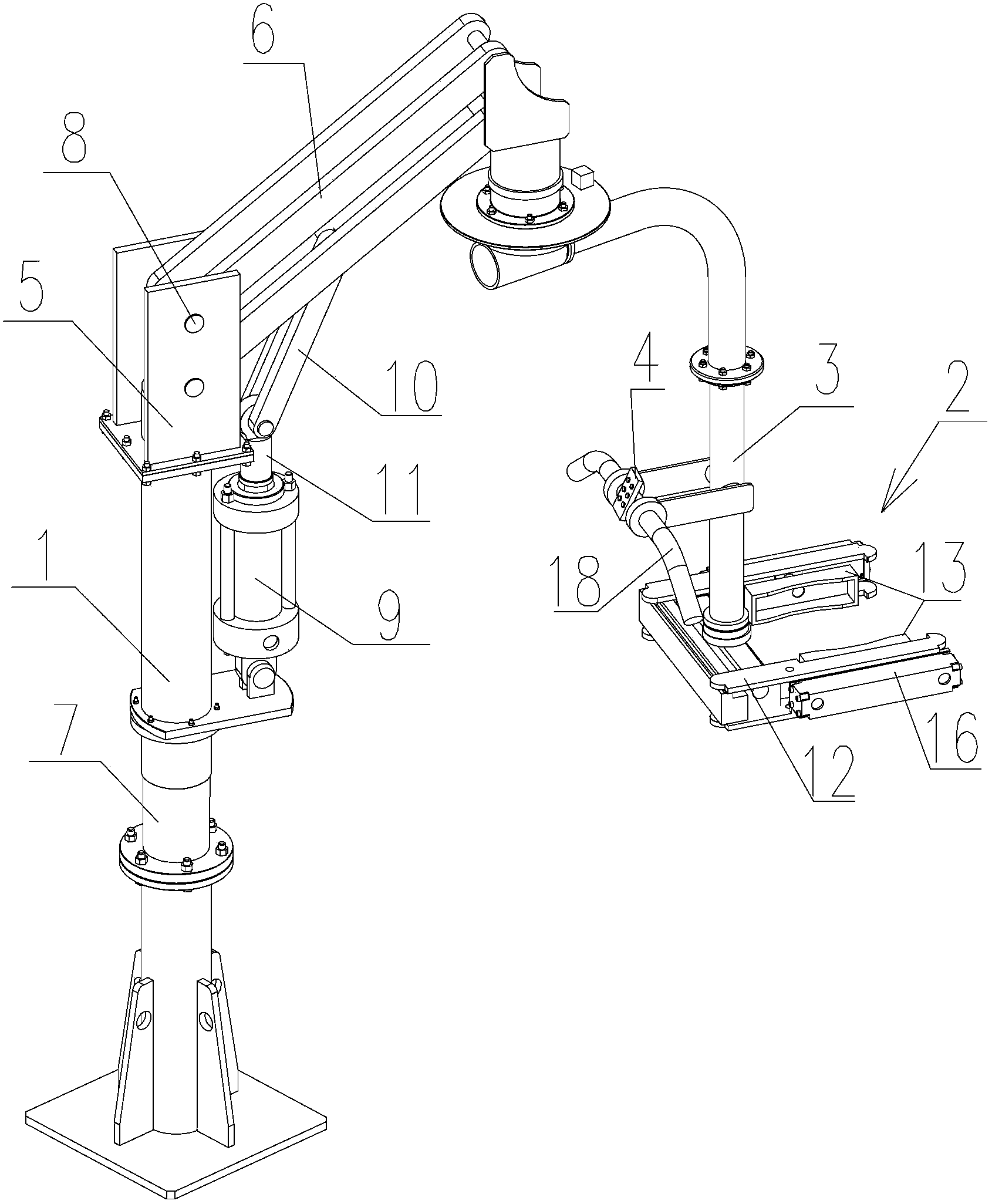
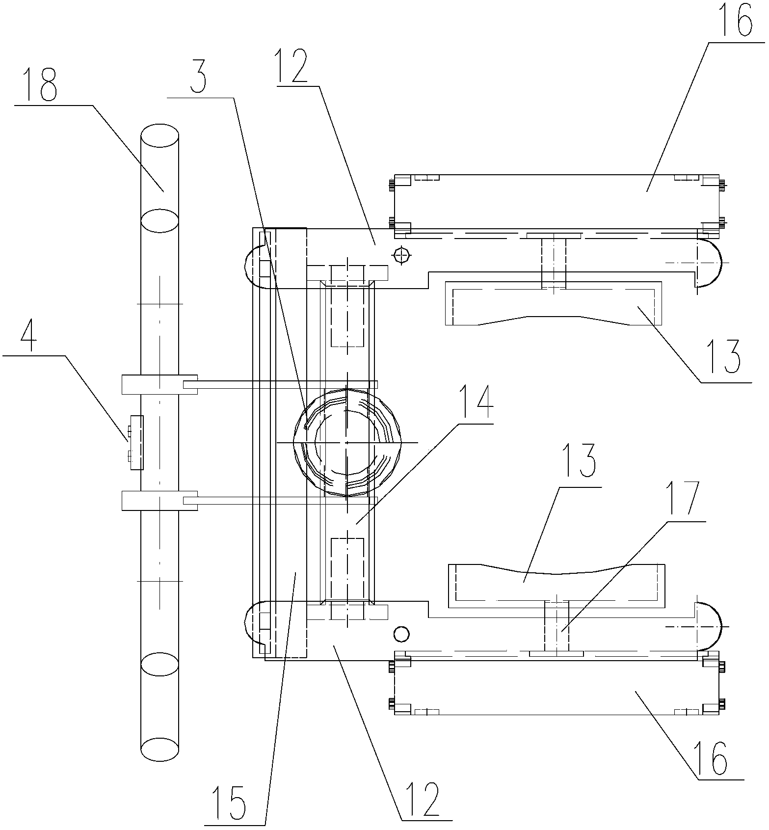
[0020] Such as figure 1 As shown, a multi-degree-of-freedom manipulator clamp includes a manipulator main body 1, a clamping mechanism 2, a connecting arm 3 for connecting the manipulator main body 1 and the clamping mechanism 2, and a controller.

[0021] Among them, such as figure 1 As shown, the manipulator mainframe 1 includes a central rotary cantilever crane 5, the cantilever crane 5 is centered on a steel column 7, the column 7 is fixed on the floor of the workshop, the cantilever 6 rotates 360 degrees around the column 7, the cantilever 6 and the column 7 The top of the cantilever is connected by a pin 8, the cantilever 6 is lifted in the vertical direction by a telescopic cylinder 9, the telescopic cylinder 9 is fixed on the column 7, the cantilever 6 is connected to the telescopic rod 11 of the telescopic cylinder 9 through the connecting rod ...


PUM


Abstract

The invention relates to a multi-freedom-degree manipulator fixture, which comprises a manipulator main machine, a clamping mechanism, a connecting arm which is used for connecting the manipulator main machine and the clamping mechanism, and a controller. The clamping mechanism comprises a pair of rotatable grips which is used for clamping a workpiece, a clamping device which is used for adjusting X-axis distance between the two grips, and a moving device which is used for driving the grips to move along a Y-axis, wherein the clamping device and the moving device are electrically connected with the controller. The multi-freedom-degree manipulator fixture has the advantages that the structure is simple, the multi-freedom-degree clamping of workpieces with different sizes and shapes can be realized, the operation is safe and convenient to perform, the universality is high, the grips can move linearly along the Y-axis, the requirement on the fine adjustment of the workpieces during clamping and placing, the 180-degree turnover of the workpieces can be realized, the clamping force of the grips can also be adjusted and the requirement on different clamping force for clamping different workpieces is met.

Description

Technical field [0001] The invention relates to a clamp, in particular to a multi-degree-of-freedom manipulator clamp. Background technique [0002] Existing power-assisted manipulator jaw clamping fixture mechanisms are mostly dedicated fixtures with low versatility. Generally, there are the following problems: 1. The mechanism has a small degree of freedom and is difficult to adapt to the needs of workpieces of various sizes. 2. It is difficult to turn the workpiece. Even if it is turned, it is difficult to accurately locate the position of the workpiece. After turning the workpiece, it needs to be repositioned and then clamped. The clamping efficiency is not high, and it is time-consuming and difficult to operate. 3. It is difficult to adjust the clamping force of the workpiece. Different workpieces have different requirements on the surface quality of the workpiece and the rigidity of the workpiece. Different requirements are put forward for the clamping force of the manipula...

Claims


Application Information

Patent Timeline
Patent Type & Authority Applications(China)
IPC IPC(8): B25J9/08B25J9/02B25J15/08
Inventor 敬俊娥程芳玲鲁宁魏京利李翊
Owner CRRC QINGDAO SIFANG CO LTD
Learn More