
Method for controlling hump rolling and classification tail plane rolling sub-region operation of railway classification yard

The technology of hump slip and plane slip is applied in the field of operation control of hump slip and braided tail plane slip in railway marshalling yard, which can solve the problems of inability to realize automatic connection, low labor efficiency, hidden danger of iron shoes, etc. To achieve the effect of preventing vehicles from cross-regional conflict operations, improving labor efficiency, and saving personnel expenses

Active Publication Date: 2014-01-01
中铁武汉勘察设计院有限公司
View PDF3 Cites 12 Cited by
  • Summary
  • Abstract
  • Description
  • Claims
  • Application Information

AI Technical Summary

Problems solved by technology

This method is prone to safety problems such as derailment caused by stuck shoes, collision caused by improper braking, and reversed iron shoes caused by forgetting to withdraw the iron shoes. At the same time, it will cause damage to the wheel tread.
; The loss of iron shoes has a serious safety hazard to the main line of the railway
Manually controlled iron shoe speed regulation cannot realize automatic coupling, which is inefficient
Iron shoe braking requires one or two experienced personnel to place the iron shoes at each lane at the end of the marshalling yard, and the labor efficiency is low

Method used


Image

  • Method for controlling hump rolling and classification tail plane rolling sub-region operation of railway classification yard
  • Method for controlling hump rolling and classification tail plane rolling sub-region operation of railway classification yard

Examples


Embodiment Construction

[0016] The invention will be further described below in conjunction with the accompanying drawings and embodiments.

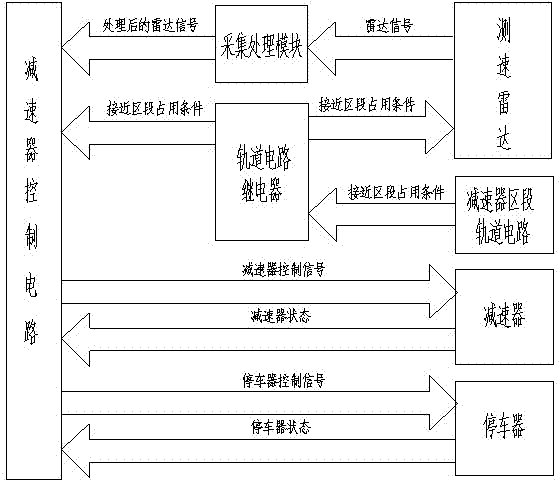
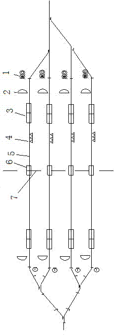
[0017] The method of the present invention is as follows: set a divisional operation demarcation point on the same track in the railway marshalling yard, set a parking device at the divisional operation demarcation point, and the plane sliding speed regulation area is formed between the weaving tail lead-out line and the divisional operation demarcation point, and the marshalling yard head The hump drop-off area is between the hump at the top and the dividing point of the divisional operation; a clamp-type reducer is set at the entrance of the tailing yard and 80 to 120m away from the shunting signal machine of the tailing yard, and in the target area of ​​the reducer A deceleration roof is set at the slope change point section from the terminal to the tailing yard, and a speed measuring radar is set between the shunting signal machine and the clamp-type reducer...


PUM


Abstract

The invention discloses a method for controlling plane rolling and hump rolling sub-region operation on railway vehicles. The method includes setting boundary points on the same station tracks of a railway classification yard, and setting parking devices at the boundary points; setting clamp type speed reducers at inlets of the station tracks of a classification tail yard, setting dowty retarders among speed reducer targeting area terminals and grade change point regions, setting speed measuring radar devices among shunting signal machines and the clamp type speed reducers, and arranging speed reducer section rail circuits and speed reducer control circuits; performing speed regulation operation on the vehicles by the aid of the speed reducers, the speed measuring radar devices, the speed reducer section rail circuits and the speed reducer control circuits during hump rolling operation; performing plane rolling speed regulation operation on the vehicles by the aid of the speed reducers, the speed measuring radar devices, the speed reducer section rail circuits and the speed reducer control circuits during classification tail plane rolling operation. The method has the advantages that the labor efficiency can be greatly improved, iron shoes can be omitted, potential safety hazards of operation can be reduced, and the safety level can be upgraded.

Description

Technical field [0001] The invention relates to a method for controlling partitioned operation of hump slipping and tail plane slipping in a railway marshalling yard, which is applied to partition protection and hump spanning of the speed regulation operation of hump slipping and automatic speed regulation of tail flat slipping in railway freight marshalling stations Prevent the vehicle from slipping away during the sliding operation. Background technique [0002] The hump operation in the railway marshalling yard is divided into two areas: the shunting area at the head of the hump and the shunting area at the rear. A safety demarcation point is set in the middle of the two areas to separate operations. When trains operate across regions, they need to go through manual procedures to operate across regions. The vehicle crossing protection at the demarcation point is still manual, with low labor rate and high risk factor. [0003] At present, the deceleration control of the...

Claims


Application Information

Patent Timeline
Patent Type & Authority Applications(China)
IPC IPC(8): B61L23/00B61K7/02
Inventor 张佳楠王增力陆文庆卢刚蔡云峰石玉莹陈安观方亚非
Owner 中铁武汉勘察设计院有限公司
Learn More