Film slitting machine with finished film take-up shafts and edge film take-up shafts separate from each other

A technology of winding shaft and slitting machine, which is applied in the directions of winding strips, thin material handling, transportation and packaging, etc. It can solve the problems of unwinding, uneven edges and inner wrinkles of finished film rolls, and achieve fast production speed, The effect of low cost and high work efficiency

Active Publication Date: 2014-01-01
ANHUI SAFE ELECTRONICS
View PDF8 Cites 1 Cited by
  • Summary
  • Abstract
  • Description
  • Claims
  • Application Information

AI Technical Summary

Problems solved by technology

[0005] The present invention is aimed at the deficiencies of the prior art, and provides a film slitting machine in which the finished film winding shaft is separated from the edge film winding shaft, so as to overcome the problems of the finished film when the edge film roll breaks and collapses in the prior art. The roll will produce defects such as loose rolls, inner wrinkles, and uneven edges, which will lead to the problem of scrapping

Method used


Image

  • Film slitting machine with finished film take-up shafts and edge film take-up shafts separate from each other
  • Film slitting machine with finished film take-up shafts and edge film take-up shafts separate from each other
  • Film slitting machine with finished film take-up shafts and edge film take-up shafts separate from each other

Examples


Embodiment Construction

[0019] The content of the present invention will be described below in conjunction with specific embodiments.

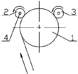
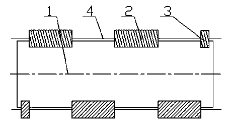
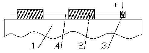
[0020] Such as Figure 4-5 As shown, it is a structural schematic diagram of a film slitting machine in which the finished film winding shaft and the edge film winding shaft are separated according to the present invention. The film slitting machine in which the finished film rewinding shaft and the edge film rewinding shaft are separated according to the present invention comprises: a winding touch roll 1, a finished film roll 2, an edge film roll 3, a finished film reel 4, an edge film reel 7, There are multiple finished film rolls 2, two edge film rolls 3, and two finished film winding shafts 4, which are respectively arranged on both sides of the winding contact roll 1 and are connected with the winding rolls. The contact roller 1 is axially parallel, and the finished film rolls 2 are alternately arranged on two finished film winding shafts 4, and the edge film ...


PUM


Abstract

The invention discloses a film slitting machine with finished film take-up shafts and edge film take-up shafts separate from each other. The film slitting machine comprises a take-up contact roller, a plurality of finished film rolls, two edge film rolls, two finished film take-up shafts, and two edge film take-up shafts. The finished film take-up shafts are disposed on two sides of the take-up contact roller and axially parallel to the take-up contact roller. The finished film rolls alternately disposed on the two finished film take-up shafts at intervals. The edge film take-up shafts are disposed around the take-up contact roller and axially parallel to the take-up contact roller. The two edge film rolls are disposed on the edge film take-up shafts and arranged at two ends of the take-up contact roller respectively. The film slitting machine has the function that take-up defects of the edge film roll are prevented from causing quality problem in the finished film rolls.

Description

technical field [0001] The invention relates to a film slitting machine in which a finished film winding shaft is separated from an edge film winding shaft, and belongs to the technical field of film cutting equipment. Background technique [0002] Metallized film cutting equipment commonly used in the prior art, specifically the J70820-I / zF metallized film cutting machine produced by Xi’an Metro Technology Co., Ltd., its working principle is to put the semi-finished film roll on the On the unwinding shaft of the slitting machine, the film is cut into predetermined specifications after running through a series of guide rollers, flattening rollers, knife groove rollers, pressure rollers, winding rollers and other roller groups. The entire process of film from rolling to winding has strict requirements on process and equipment parameters, especially in the winding stage, the winding structure of the film will directly affect the quality of the finished film roll. [0003] The...

Claims


Application Information

Patent Timeline
Patent Type & Authority Applications(China)
IPC IPC(8): B65H18/08
Inventor 庄如琴周峰
Owner ANHUI SAFE ELECTRONICS
Why Eureka
Try Eureka