Rotary-cutting type pipeline cleaner

A pipe dredge and rotary cutting technology, which is applied in the field of pipeline dredging propulsion devices, can solve problems such as low efficiency, low efficiency, and high cost, and achieve the effects of convenient use, simple structure, and low labor cost

Active Publication Date: 2014-01-01
河南绿城龙飞实业有限公司
View PDF7 Cites 3 Cited by
  • Summary
  • Abstract
  • Description
  • Claims
  • Application Information

AI Technical Summary

Problems solved by technology

Manual dredging refers to dredging by putting net pull rope bamboo strips in the pipeline. The disadvantage is that the labor intensity of workers is high and the efficiency is very low; mechanical equipment dredging is a kind of imported high-pressure water flushing machinery from abroad. To dredge the pipeline, the advantage is high efficiency, and its disadvantage is high cost. In addition, when the pipeline encounters softer elastic obstacles or relatively hard obstacles (such as bricks and cement flowing into the pipeline during large-scale construction ) the effect is not ideal; in addition, there is also the use of hose vibration to dredge, although the dredging efficiency is high, but it cannot dredge long-distance pipelines
Based on the use of the above machines, it is not ideal, so a mechanical device that can dredge long distances and has a good dredging effect on softer elastic obstacles or harder obstacles is needed
[0003] At the same time, in terms of cost, the original manual dredging required more than 8 people to work at the same time, the workload was heavy, the cost was high, the efficiency was low, and the cycle of dredging the pipeline was long, which seriously affected the surrounding traffic and the lives of residents. Blockage makes the entire drainage environment worse. Therefore, a mechanical device that can reduce labor intensity, improve labor efficiency, reduce dredging costs, and dredge pipes is needed.

Method used


Image

  • Rotary-cutting type pipeline cleaner
  • Rotary-cutting type pipeline cleaner
  • Rotary-cutting type pipeline cleaner

Examples


Embodiment 1

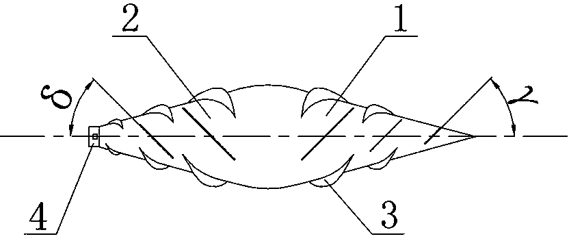
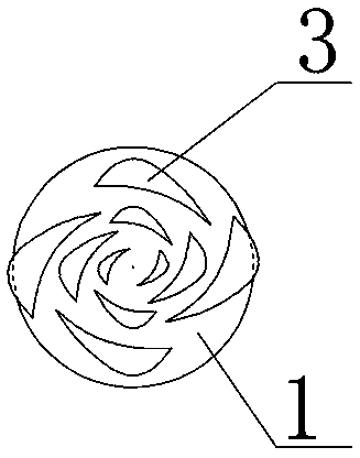
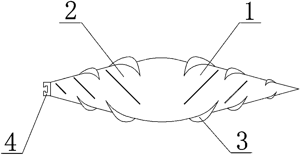
[0030] see Figure 1 to Figure 9 , a rotary-cutting type pipeline dredger of the present invention, comprising a shuttle-shaped dredge body, a rotary-cut blade 3 arranged outside the dredge body and a quick joint base at the bottom of the dredge, the rotary-cut blade 3 It includes a cutting part and a connecting part 303 matched and fixed with the dredge body. The cutting part includes a main cutting edge 301 and an auxiliary cutting edge 302. The two vertices of the connecting part of the rotary cutting blade 3 and the highest point of the cutting part relative to the connecting part form an included angle β It is an obtuse triangle of 125°~135°, and the angle α formed by the obtuse triangle relative to the side of the main cutting edge 301 and the side where the two vertices of the connecting portion are located is 15°~20°. The dredger body is composed of a conical advancing section 1 and an inverted conical exiting section 2. The rotary cutting blades 3 arranged on the adva...

Embodiment 2

[0034] The structure of embodiment two is basically the same as that of embodiment one, and the similarities will not be repeated. The difference is that the number of rotary cutting blades 3 on the advancing section 1 and the exiting section 2 is 12, and the rotary cutting blades 3 are 12. The cutting blades 3 are arranged in four rows on the outer surfaces of the advancing section 1 and the exiting section 2, and the four-row rotary cutting blades 3 have three single rows.


PUM


Abstract

The invention relates to a pipeline cleaning and propelling device, in particular to a rotary-cutting type pipeline cleaner. The rotary-cutting type pipeline cleaner comprises a fusiform cleaner body, rotary-cutting blades and a connecting piece, the rotary-cutting blades are arranged on the surface of the cleaner body, and the connecting piece fixedly connected with a cleaning trolley is arranged at the bottom of the cleaner. The cleaner body is composed of a pyramidal propelling section and an inverted pyramidal retreating section, and the rotary-cutting blades on the propelling section array in the clockwise direction, while the rotary-cutting blades on the retreating section array in the anti-clockwise direction. By the progressive propelling mode of drilling and cutting, any drain pipeline blockage problems can be solved. Meanwhile, the fusiform cleaner body capable of cleaning and cutting in the process of propelling and retreating is adopted, so that the problem that the blockage is further worsened to cause stoppage due to a traditional cleaning mode is solved thoroughly.

Description

technical field [0001] The invention relates to a pipeline dredging propelling device, in particular to a rotary cutting type pipeline dredger for shredding blocked sundries and pushing them into a conduit. Background technique [0002] At present, the dredging of water drainage pipes for urban residents is divided into two types: manual dredging and mechanical equipment dredging. Manual dredging refers to dredging by putting net pull rope bamboo strips in the pipeline. The disadvantage is that the labor intensity of workers is high and the efficiency is very low; mechanical equipment dredging is a kind of imported high-pressure water flushing machinery from abroad. To dredge the pipeline, the advantage is high efficiency, and its disadvantage is high cost. In addition, when the pipeline encounters softer elastic obstacles or relatively hard obstacles (such as bricks and cement flowing into the pipeline during large-scale construction ) effect is not ideal; in addition, the...

Claims


Application Information

Patent Timeline
Patent Type & Authority Applications(China)
IPC IPC(8): E03F7/10E03C1/302
Inventor 吴爱雯吴彦云雷建强芦子荣
Owner 河南绿城龙飞实业有限公司
Why Eureka
Try Eureka