Engine balance shaft mechanism and engine assembly

A technology for balancing shafts and engines, applied in engine components, machines/engines, mechanical equipment, etc., can solve the problems of cumbersome manufacturing and assembly processes, low space utilization, and many parts, and achieve compact structure and small footprint.

Active Publication Date: 2014-01-01
ZHEJIANG GEELY HOLDING (GROUP) CO LTD +1
View PDF6 Cites 12 Cited by
  • Summary
  • Abstract
  • Description
  • Claims
  • Application Information

AI Technical Summary

Problems solved by technology

This engine balance shaft mechanism itself has complex structure, many parts, high cost, and complicated manufacturing and assembly processes; moreover, because the balance shaft is arranged at the lower part of the engine, the height of the entire engine is increased, and the zero point far away from the center of the engine will be caused by the increase in height. The increased component amplitude increases the possibility of component damage, and the space utilization rate is low, which makes the engine structure not compact enough; in addition, the chain transmission mechanism is complicated, and the mechanical loss power caused by the chain tensioning mechanism is large, and the engine fuel consumption Affected

Method used


Image

  • Engine balance shaft mechanism and engine assembly
  • Engine balance shaft mechanism and engine assembly
  • Engine balance shaft mechanism and engine assembly

Examples


Embodiment Construction

[0032] In order to further explain the technical means and functions adopted by the present invention to achieve the intended purpose of the invention, the specific embodiments, structures, features and functions of the present invention will be described in detail below in conjunction with the accompanying drawings and preferred embodiments.

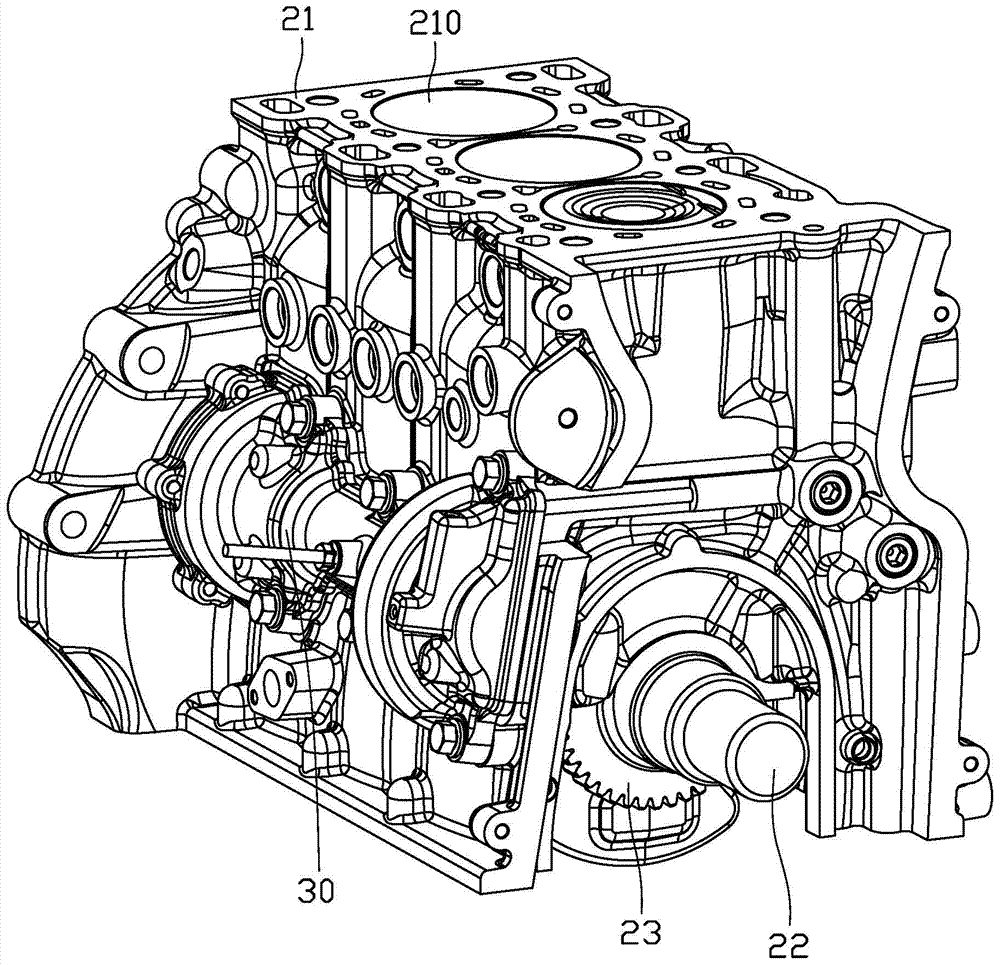
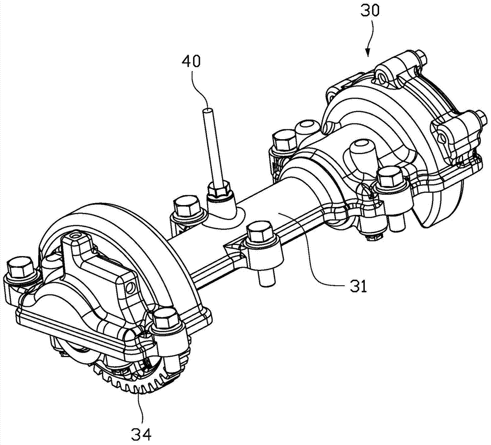
[0033] see figure 1 , The engine assembly of the embodiment of the present invention includes a cylinder block 21 , a crankshaft 22 , a crankshaft gear 23 and an engine balance shaft mechanism 30 . It should be noted that the engine assembly also includes other components such as piston assemblies, which are not shown in the figure for brevity.

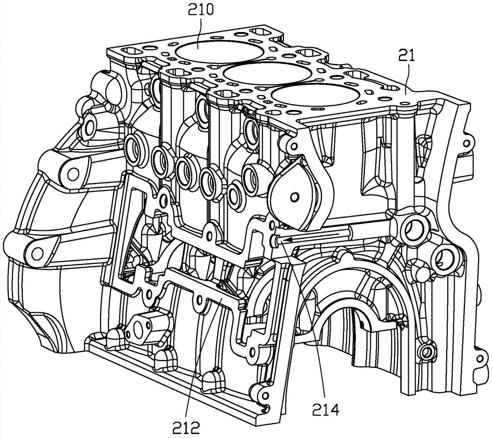
[0034] Please refer to figure 2 , the cylinder block 21 is provided with a plurality of cylinders 210, for example, figure 1 and figure 2 3 cylinders 210 are shown. The crankshaft 22 is disposed inside the cylinder block 21 and is disposed at the bottom of the cylinder block 21 . A pisto...


PUM


Abstract

An engine balance shaft mechanism comprises a balance shaft shell, a balance shaft, a rear balance weight, a balance shaft gar and a front balance weight. The balance shaft comprises a front end, a rear end, and a middle connecting segment connected between the front end and the rear end. The rear balance weight is fixed at the rear end of the balance shaft. The balance shaft gear and the front balance weight are fixed at the front end of the balance shaft. The front balance weight and the rear balance weight are disposed in an angular opposition form. The balance shaft shell covers the balance shaft, the rear balance weight, the balance shaft gear and the front balance weight. The side of the balance shaft shell is provided with a first mounting face used for being mounted on the side of a cylinder block of an engine; the side of the cylinder block is provided with a second mounting face; the first mounting face is in mounting fit with the second mounting face. The engine balance shaft mechanism is simple in structure, small in size, and convenient to arrange. The invention further relates to an engine assembly.

Description

technical field [0001] The invention relates to the technical field of automobiles, and in particular to an engine balance shaft mechanism and an engine assembly. Background technique [0002] Engine vibration and noise directly affect the comfort of the vehicle and the structural strength of the engine itself. Excessive vibration will lead to the service life and performance of related parts. Generally speaking, it is difficult to balance the reciprocating inertial force of the crank-link mechanism of an engine with an odd number of cylinders, and it is usually necessary to add a balance shaft to balance it, such as an engine with 3 cylinders and 5 cylinders. [0003] The existing engine balance shaft mechanism is arranged in the lower part of the engine, including parts such as balance shaft housing, balance shaft, counterweight, drive chain, gear, etc., and its working principle is that the crankshaft drives the chain usually to drive the balance shaft mechanism. This en...

Claims


Application Information

Patent Timeline
Patent Type & Authority Applications(China)
IPC IPC(8): F02B75/06F16F15/26F02F1/00
Inventor 白广松袁爽由毅沈源冯擎峰
Owner ZHEJIANG GEELY HOLDING (GROUP) CO LTD
Why Eureka
Try Eureka