Sealing Mechanism for Rotary Handling Devices

A technology of rotating processing devices and sealing components, which is applied to centrifuges with rotating drums, engine seals, centrifuges, etc., can solve problems such as loose sealing characteristics, insufficient sealing characteristics, and poor pressure resistance, and achieve suppression Reduced sealing properties, suppression of leakage of contents, and reduction in diameter

Active Publication Date: 2016-03-09
TOMOE ENGINEERING CO LTD
View PDF5 Cites 0 Cited by
  • Summary
  • Abstract
  • Description
  • Claims
  • Application Information

AI Technical Summary

Problems solved by technology

[0005] However, the sealing member that seals the gap between the opening of the case and the connecting portion has a problem that the sealing performance is not necessarily sufficient.
Especially in the case of high pressure (for example, 0.6MPa or more) operating conditions, leakage due to poor pressure resistance may occur
In addition, in a device having a rotating body, since the rotating body moves eccentrically with respect to the housing during rotation, looseness may occur in the unit that clamps the clamping portion, thereby reducing the sealing performance.
In the case of a vertical settler such as Patent Document 1, since the rotating drum, which is a rotating body, is supported by a suspension, shaking (vibration) generated during the rotating operation often causes a decrease in sealing properties.
[0006] In addition, the conventional sealing member has the problem that the surface pressure on the clamped surface is high, and a high torque is required for tightening bolts and the like.
When the surface pressure is high, there are many cases of poor installation and loosening of bolts, etc., and there is a problem that the installation work to the device is not easy.

Method used


Image

  • Sealing Mechanism for Rotary Handling Devices
  • Sealing Mechanism for Rotary Handling Devices
  • Sealing Mechanism for Rotary Handling Devices

Examples


Embodiment

[0047] Next, examples performed to confirm the effects of the present invention will be described.

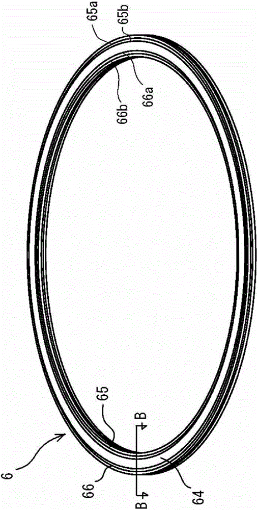
[0048] Such as Figure 6 As shown, in addition to confirming the sealing member 6 (a) of the above-mentioned embodiment, the present inventors also confirmed that there are two peaks (b) only on the upper surface, one peak (c) on the upper and lower sides, and two peaks (c) on the lower surface only. Sealing properties of a peak (d) and a sealing member without a convex portion (e). Figure 6 The results are shown together.

[0049] For the reasons already described, the sealing member of (a) has good sealing properties based on the contact area (sealing properties: ○), and leakage due to positional displacement due to vibration or the like does not occur (stability: ○). On the other hand, when there is one peak (c) up and down, the sealing property is good (◯), but leakage due to positional displacement was confirmed (stability: x). In addition, the flat seal member (e) wit...


PUM


Abstract

The object of the present invention is to provide an improved sealing property when a ring-shaped sealing member seals a gap between an opening of a casing serving as a pressure vessel and a connection portion of a rotation processing mechanism, which extends through the opening. The sealing member a three-layer structure in which a layer of a fluorine-base resin material, a layer of a rubber-base resin material and a base fabric of a nylon-base material are deposited in that order from a side contact with an internal atmosphere within the casing and the cross sectional shape of the sealing member is designed to have a convexly curved center portion and the opposing portions on both side of the central portion, so that the sealing property at the opening of the casing where the connection portion of the rotation processing mechanism can be enhanced. In addition, the degradation of the sealing property due to any shakes (vibrations) which may occur during the rotational movement of the casing.

Description

technical field [0001] The present invention relates to a rotary processing device such as a centrifuge. Background technique [0002] For example, a decanter type centrifuge disclosed in Patent Document 1 is a rotary treatment device that applies centrifugal force to a liquid to be treated to perform a separation operation. In the centrifuge, a bowl (bowl) and a screw conveyor (screw conveyor) as a rotating body are arranged inside a casing, and a drive mechanism (for example, a drive motor) for rotating the bowl is arranged outside the casing. The screw conveyor is rotated with a relative differential speed to the drum by transmitting the power of the drive motor through a gear box as a differential speed generating device. A shaft serving as a rotating shaft of the drum is pivotally supported by a connecting portion penetrating through the opening of the casing, and power of the drive motor is transmitted to an end portion of the shaft extending outside the casing. The ...

Claims


Application Information

Patent Timeline
Patent Type & Authority Patents(China)
IPC IPC(8): F16J15/20B04B7/00
CPCB04B1/20B04B7/00
Inventor 羽岛信介杉野荣一高野直文
Owner TOMOE ENGINEERING CO LTD
Why Eureka
Try Eureka