Check patentability & draft patents in minutes with Patsnap Eureka AI!

Backlight module

A technology of backlight module and light source, applied in the field of direct type backlight module, can solve the problems of unevenness, MURA backlight module brightness, etc., and achieve the effect of reducing cost

Inactive Publication Date: 2014-01-01
TOP VICTORY INVESTMENTS
View PDF7 Cites 2 Cited by
  • Summary
  • Abstract
  • Description
  • Claims
  • Application Information

AI Technical Summary

Problems solved by technology

[0005] However, under this existing structural design, for the sake of cost and thinning, measures such as reducing the number of optical films or LED chips are often adopted, so MURA phenomenon (uneven brightness emitted by the backlight module) is prone to occur.

Method used


Image

  • Backlight module
  • Backlight module
  • Backlight module

Examples


Embodiment Construction

[0025] The present invention will be described in detail below in conjunction with the accompanying drawings and embodiments.

[0026] Before the present invention is described in detail, it should be noted that in the following description, similar components are denoted by the same numerals.

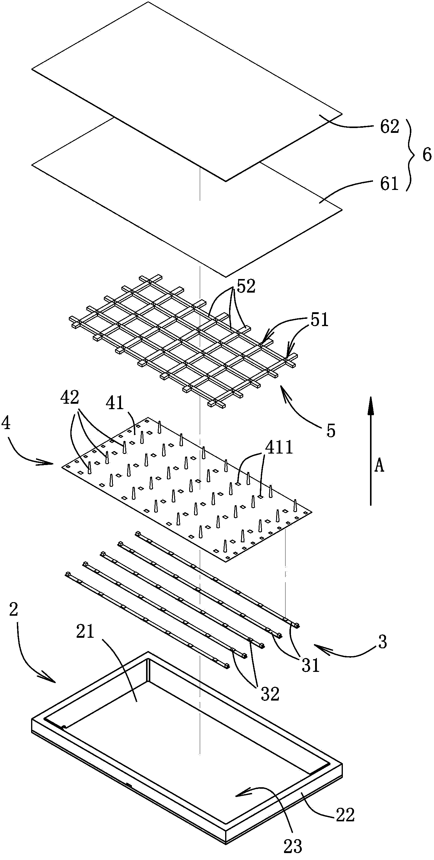
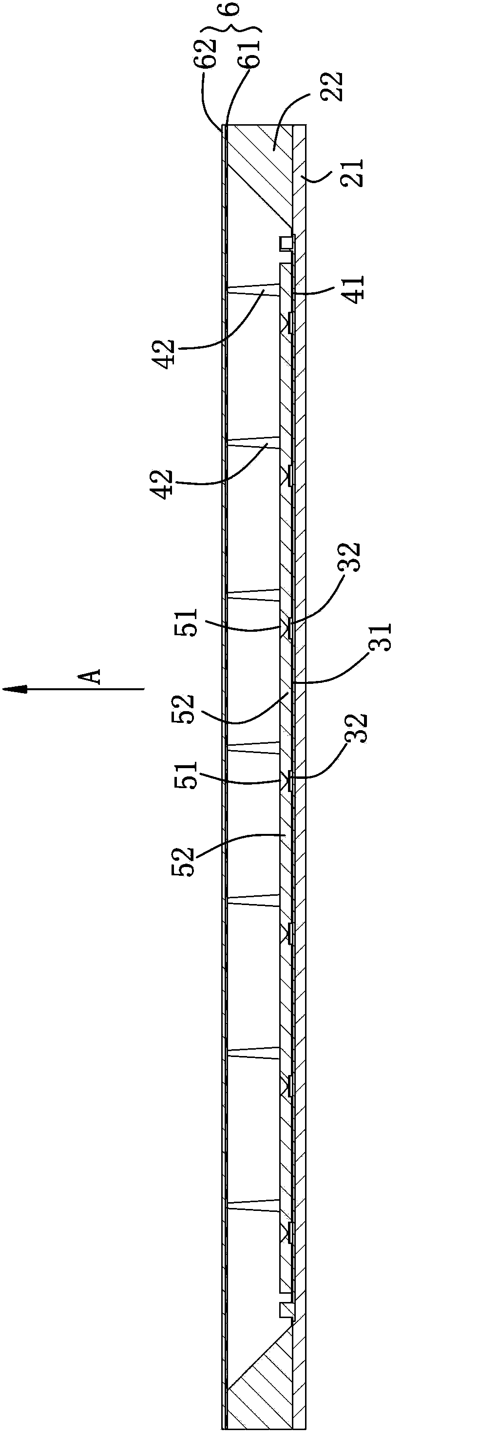
[0027] refer to figure 2 and image 3 , the first preferred embodiment of the backlight module of the present invention includes a casing 2 , a light source 3 , a supporting unit 4 , a secondary optical component 5 and an optical film set 6 .

[0028] The housing 2 has a base wall 21 , a surrounding wall 22 extending from the base wall 21 toward a first direction A, and an accommodating space 23 defined by the base wall 21 and the surrounding wall 22 . And the accommodating space 23 is for accommodating the light source 3 , the supporting unit 4 , the secondary optical component 5 and the optical film group 6 along the first direction A in sequence.

[0029] The light source 3 incl...


PUM


Abstract

A backlight module comprises a light source, an optical film assembly and a secondary optical module. The light source comprises at least one circuit board and a plurality of LED (light-emitting diode) chips arranged on the circuit board. The optical film assembly faces the light source and is perpendicular to a first direction. The secondary optical module is made of transparent molecular material and arranged between the light source and the optical film assembly, and comprises a plurality of blocky light-splitting bodies and a plurality of strip-shaped light guide bodies. The light-splitting bodies respectively correspond to one LED chip, each light-splitting body is provided with a recess, the opening of which is aimed at the optical film assembly, and moreover, the cross section of the recess is gradually reduced along a direction close to the corresponding LED chip. The strip-shaped light guide bodies are respectively connected with the sides of the light-splitting bodies. The backlight module has the advantage that the secondary optical module arranged between the light source and the optical film assembly is utilized to split light, so that light can uniformly enter the optical film assembly, and thereby the quantity of the LED chips or the optical film assembly in use is reduced.

Description

technical field [0001] The invention relates to a backlight module, in particular to a direct type backlight module. Background technique [0002] With the advancement of technology, liquid crystal panels are widely used in today's life, such as mobile phones, notebook computers, personal computers and televisions and other electronic products. However, since the liquid crystal panel itself does not emit light, a backlight module is generally used to provide a light source for the liquid crystal panel to achieve the display effect of the liquid crystal panel. [0003] Generally, backlight modules can be divided into two types, one is a direct-type backlight module usually used for large-size liquid crystal panels, and the other is an edge-type backlight module usually used for small-size liquid crystal panels. [0004] figure 1 It is a schematic diagram of a conventional direct-type backlight module 1 , which includes a reflector 11 , a light source 12 and an optical film ...

Claims


Application Information

Patent Timeline
IPC IPC(8): F21S8/00F21V13/00G02F1/13357F21Y101/02
Inventor 林忠志王铭禧王荷正
Owner TOP VICTORY INVESTMENTS
Features
  • R&D
  • Intellectual Property
  • Life Sciences
  • Materials
  • Tech Scout
  • Unparalleled Data Quality
  • Higher Quality Content
  • 60% Fewer Hallucinations
Learn More