
Method and system for allocation of reactive compensation capacity of microgrid

A technology of compensation capacity and configuration method, applied in the field of power grid, can solve problems such as uneven distribution of micro-grid system power flow, poor stability of micro-grid, and fluctuation of reactive power in micro-grid

Active Publication Date: 2015-02-11
CHINA ENERGY ENG GRP GUANGDONG ELECTRIC POWER DESIGN INST CO LTD
View PDF2 Cites 0 Cited by
  • Summary
  • Abstract
  • Description
  • Claims
  • Application Information

AI Technical Summary

Problems solved by technology

[0004] Traditional microgrids, such as island-type microgrids, have small system capacity and low system inertia. Due to access to uncontrollable distributed power sources, random fluctuations in DG output power will cause reactive power fluctuations in the entire microgrid. Causes uneven distribution of power flow in the microgrid system, resulting in poor stability of the microgrid

Method used


Image

  • Method and system for allocation of reactive compensation capacity of microgrid
  • Method and system for allocation of reactive compensation capacity of microgrid
  • Method and system for allocation of reactive compensation capacity of microgrid

Examples


Embodiment Construction

[0073] In order to make the above objects, features and advantages of the present invention more comprehensible, specific implementations of the present invention will be described in detail below in conjunction with the accompanying drawings. In the following description, numerous specific details are set forth in order to provide a thorough understanding of the present invention. However, the present invention can be implemented in many other ways different from those described here, and those skilled in the art can make similar improvements without departing from the connotation of the present invention, so the present invention is not limited by the specific embodiments disclosed below.

[0074] Unless otherwise defined, all technical and scientific terms used herein have the same meaning as commonly understood by one of ordinary skill in the technical field of the invention. The terms used herein in the description of the present invention are for the purpose of describin...


PUM


Abstract

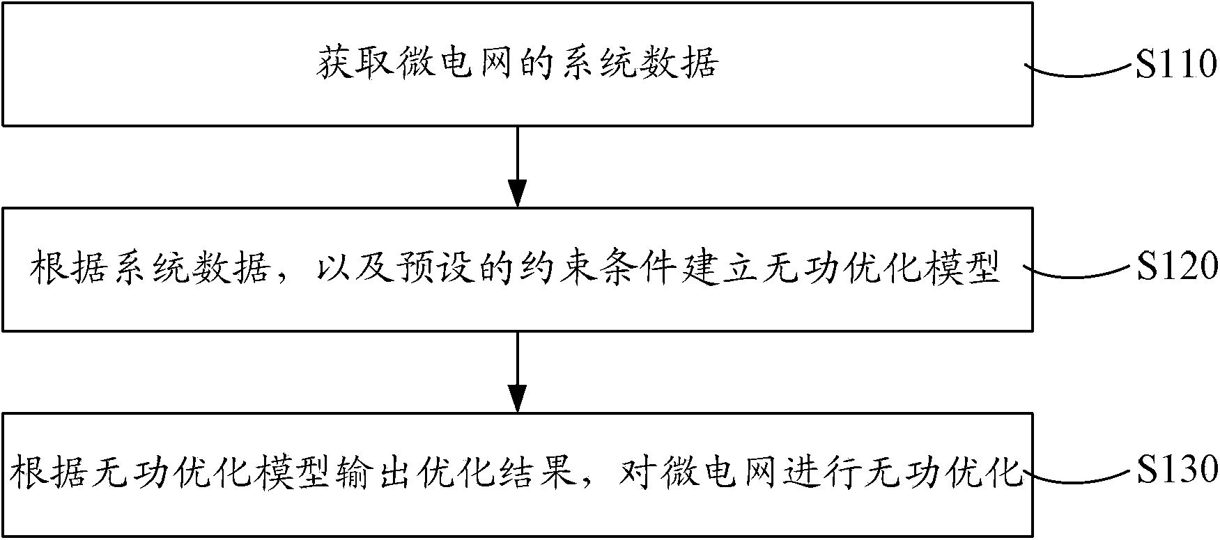
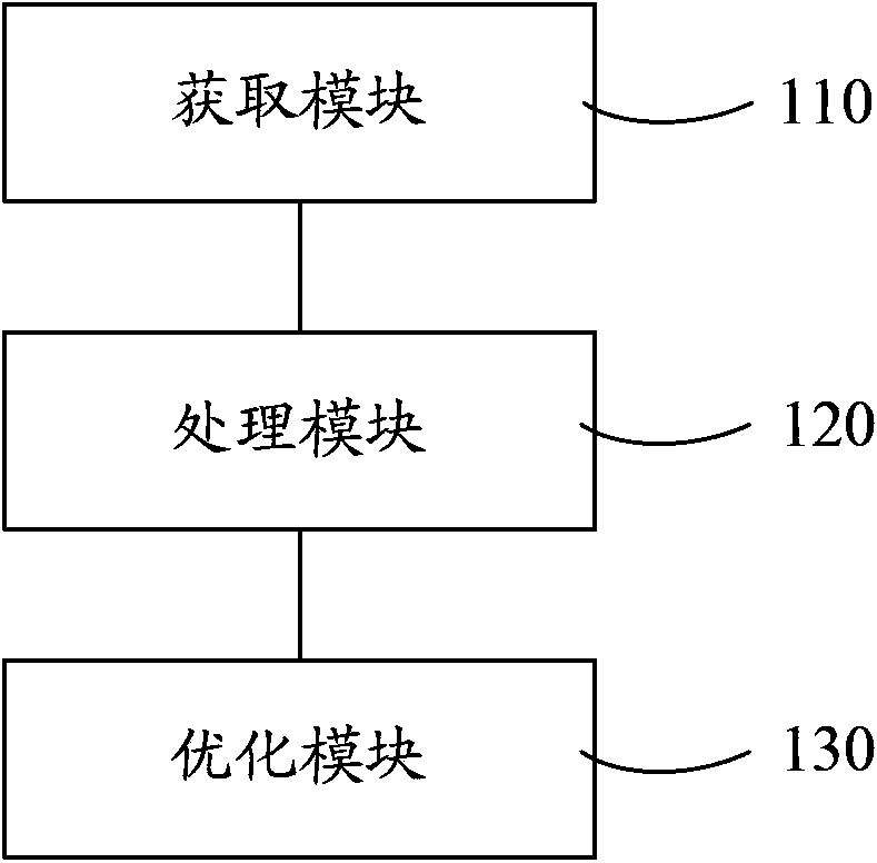
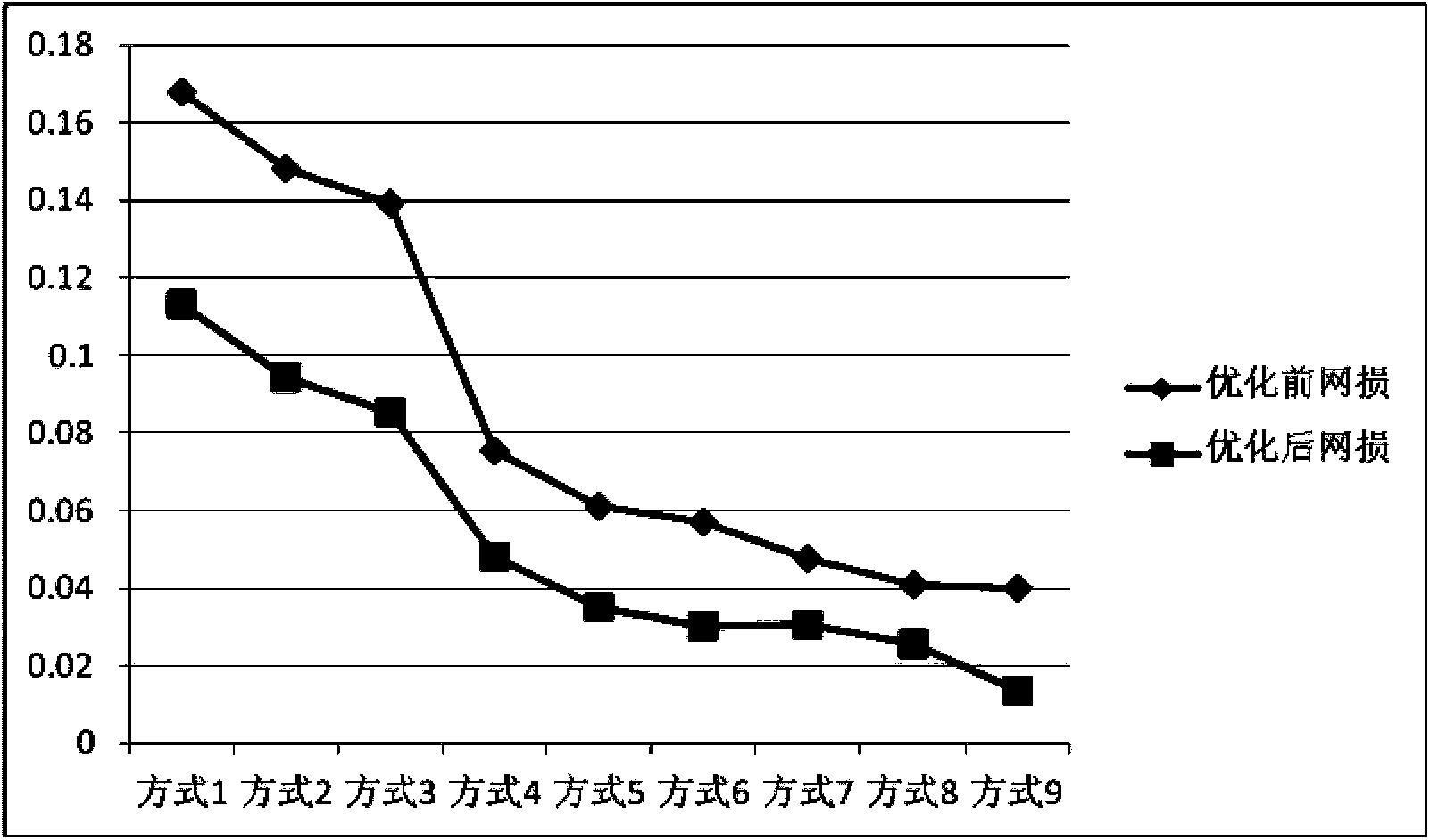
The invention discloses a method and system for allocation of the reactive compensation capacity of a microgrid. According to the method and system for allocation of the reactive compensation capacity of the microgrid, system data of the microgrid are obtained by an acquisition module, a reactive power optimization model is established by a processing module according to the system data and preset constraint conditions, an optimization result is output by an optimization module according to the reactive power optimization model, and then reactive power optimization is carried out on the microgrid. According to the method and system for allocation of the reactive compensation capacity of the microgrid, reactive power optimization is carried out on the microgrid to achieve the purposes of the minimum active power loss of the microgrid and the minimum average voltage deviation of the microgrid through the reactive power optimization model, the reactive compensation capacity of a reactive compensation device when the reactive power optimization value is smallest serves as an optimization result, voltage fluctuation, caused by output fluctuation of a micro source, of the microgrid can be effectively restrained, stability of the microgrid is improved, power quality of a power supply is improved, loss of the microgrid is reduced, and the overall utilization rate of electric energy is improved.

Description

technical field [0001] The invention relates to the technical field of power grids, in particular to a method and system for configuring reactive power compensation capacity of a micro-grid. Background technique [0002] Microgrid is composed of Distributed Generation (DG), load and power transmission and distribution system. It can operate independently or in parallel with the large power grid. It is a micro power system with coordinated and optimized control functions for internal power supply and load. The microgrid can operate in parallel with the large grid or independently. [0003] Distributed power sources in microgrids mainly include micro gas turbines, fuel cells, photovoltaic power sources, and wind power generators. Microgrids can give full play to the technical, economic and environmental benefits brought by distributed power sources to power systems and users. The distributed power generation of the microgrid has many advantages such as less pollution, high re...

Claims


Application Information

Patent Timeline
Patent Type & Authority Patents(China)
IPC IPC(8): H02J3/18
CPCY02E40/30Y02P80/14
Inventor 邓长虹马占军郑训钊马庆张雪焱谭茂强廖毅庞学跃孙景强
Owner CHINA ENERGY ENG GRP GUANGDONG ELECTRIC POWER DESIGN INST CO LTD
Learn More