Brake device of linear motor

A technology of linear motors and gate devices, which is applied in the direction of electromechanical devices, electrical components, electric components, etc., can solve the problems of linear motion speed, acceleration, fast positioning accuracy and difficult breakthrough improvement, and achieve the effect of preventing safety accidents

Active Publication Date: 2014-01-01
SOUTHEAST UNIV +1
View PDF4 Cites 2 Cited by
  • Summary
  • Abstract
  • Description
  • Claims
  • Application Information

AI Technical Summary

Problems solved by technology

At present, linear actuators often use the transmission mechanism of rotating motors, worms and screw nuts. However, linear actuators that use the "rotating motor + screw" transmission method are limited by their own structure. , acceleration, fast positioning accuracy and other aspects are difficult to have a breakthrough improvement

Method used


Image

  • Brake device of linear motor
  • Brake device of linear motor
  • Brake device of linear motor

Examples


Embodiment

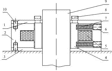
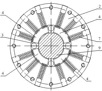
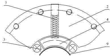
[0020] see figure 1 , The invention discloses a linear motor brake device, the brake device is integrally fixed on the linear motor housing. It includes an upper end cover 1, a static iron core 2, a lower end cover 3, a moving iron core 4, a coil 5, an adjusting nut 6, a return spring 7, bolts 8, a linear motor mover shaft 9, and countersunk screws 10.

[0021] The static iron core 2 is a ring-shaped magnetizer, and the inner ring of the static iron core 2 is embedded with a coil 5; the static iron core 2 is set outside the linear motor mover shaft 9, and the axis of the static iron core 2 coincides with the axis of the linear motor mover shaft 9, and the static iron core 2 There is a gap between the iron core 2 and the rotor shaft 9 of the linear motor.

[0022] The upper and lower surfaces of the static iron core 2 are connected with the upper end cover 1 and the lower end cover 3 through countersunk head screws 10 respectively, and the brake device as a whole is fixed on t...


PUM


Abstract

The invention relates to a brake device of a linear motor. The brake device is characterized in that the brake device is wholly fixed on a shell of the linear motor and comprises an annular static iron core and a plurality of reset springs; an active cell shaft of the linear motor is sleeved with the annular static iron core, coils are arranged on the inner ring of the annular static iron core, and moving iron cores are arranged between the inner ring of the static iron core and the active cell shaft of the linear motor; the number of the moving iron cores is matched with the number of the reset springs, the reset springs are installed in the static iron core, and the inner ends of the reset springs are connected with the moving iron cores and press the moving iron cores to the active cell shaft of the linear motor. The brake device has the advantages that when the coils are in a power-up state, the moving iron cores overcome deformation force of the reset springs through the electromagnetic effect to be attracted with the static iron core, and then the linear motor is in a non-brake state; when the coils are in a power-off state, large enough static friction force is generated between the moving iron cores and the active cell shaft of the linear motor through the pretightening pressure of the reset springs, and therefore the goal of braking the linear motor is achieved.

Description

technical field [0001] The invention relates to a brake device, in particular to a brake device for a linear motor. Background technique [0002] Electric transmission is a working method in which the motor directly drives the equipment through the transmission system to complete the action. The electric transmission is reliable and has fault tolerance. Compared with the hydraulic system, although the electric power is increased, the heat generation is small and the wear of the components is small, so the reliability of the system is improved. improve. In particular, many production machinery or special equipment require two-way drive and linear motion with a certain thrust, such as the feeding of CNC machine tools, the opening of aircraft doors, the opening and closing of high-voltage switches, and the opening and closing of electric valves, etc., can use linear motion actuator. At present, linear actuators often use the transmission mechanism of rotating motors, worms an...

Claims


Application Information

Patent Timeline
Patent Type & Authority Applications(China)
IPC IPC(8): H02K41/02
Inventor 张建忠汪仁杰吴串国饶坤蒋新苗
Owner SOUTHEAST UNIV
Why Eureka
Try Eureka