Eureka AIR delivers breakthrough ideas for toughest innovation challenges, trusted by R&D personnel around the world.

Quasi-resonant control method, system and device for switching power supply

A switching power supply, quasi-resonant technology, applied in the control/regulation system, output power conversion device, electrical components, etc., can solve the problems of poor EMI effect, increased switching frequency, large switching loss, etc., to avoid switching loss and Effects of noise problems, quantity reduction, and efficiency improvement

Active Publication Date: 2016-06-22
BYD SEMICON CO LTD
View PDF5 Cites 0 Cited by
  • Summary
  • Abstract
  • Description
  • Claims
  • Application Information

AI Technical Summary

Problems solved by technology

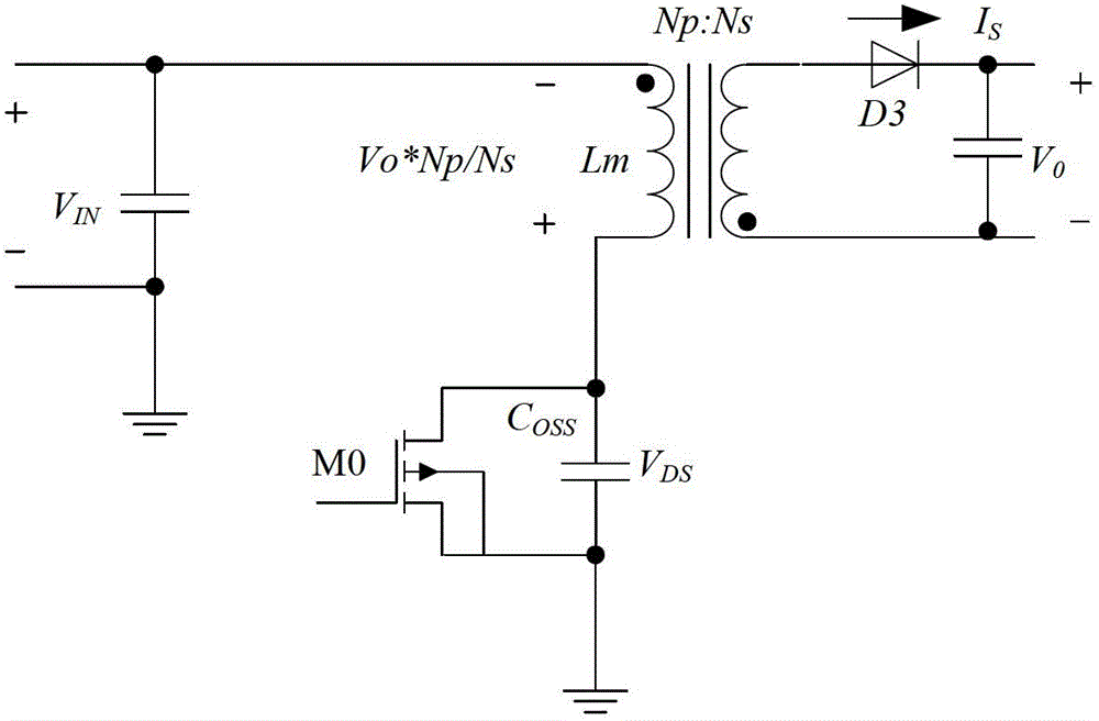
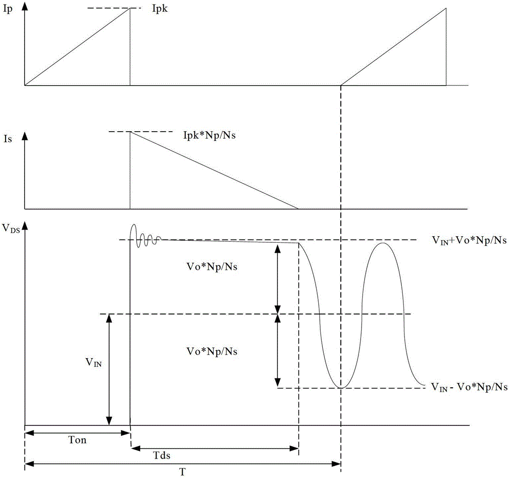
[0010] To sum up, the disadvantages of the existing technology are: the traditional PWM control method cannot realize ZVS or LVS, so the switching loss will be relatively large, and the EMI effect is not good. Although the QR mode control can realize ZVS or LVS, when When the output load is reduced or the input voltage is increased, the conduction time Ton of the MOS transistor will be reduced and the switching frequency will increase, which will lead to serious switching losses and intermittent switching and noise problems

Method used

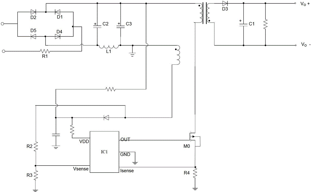

Image

  • Quasi-resonant control method, system and device for switching power supply
  • Quasi-resonant control method, system and device for switching power supply
  • Quasi-resonant control method, system and device for switching power supply

Examples


Embodiment Construction

[0036] Embodiments of the present invention are described in detail below, examples of which are shown in the drawings, wherein the same or similar reference numerals designate the same or similar elements or elements having the same or similar functions throughout. The embodiments described below by referring to the figures are exemplary only for explaining the present invention and should not be construed as limiting the present invention.

[0037] The following disclosure provides many different embodiments or examples for implementing different structures of the present invention. To simplify the disclosure of the present invention, components and arrangements of specific examples are described below. Of course, they are only examples and are not intended to limit the invention. Furthermore, the present invention may repeat reference numerals and / or letters in different instances. This repetition is for the purpose of simplicity and clarity and does not in itself indicat...


PUM


Abstract

The present invention proposes a quasi-resonance device for a switching power supply, including: a sampling module for sampling the secondary degaussing time Tds of the transformer according to the feedback signal Vsen output by the switching power supply voltage after the switch tube of the quasi-resonance module in the switching power supply is turned off; The valley sampling module is used to sample the resonance valley signal of the quasi-resonance module according to Vsen; the fixed ratio time generation module is connected with the sampling module, and is used to generate time T with a preset ratio by processing Tds; the logic processing module, the logic processing module They are respectively connected to the valley bottom sampling module and the fixed-proportion time generation module, and are used to obtain the first valley bottom signal as a switch signal after time T to turn on the switch tube. The device can improve efficiency, improve electromagnetic interference, reduce cost, and avoid switching loss and noise. The invention also provides a quasi-resonance system for switching power supply and a quasi-resonance control method for switching power supply.

Description

technical field [0001] The invention relates to the technical field of switching power supplies, in particular to a quasi-resonance device, a quasi-resonance system and a quasi-resonance control method for a switching power supply. Background technique [0002] Today, with the popularity of portable electronic devices, switching power supplies have become the main power supply solutions for these electronic devices. At present, in low-power AC / DC switching power supplies, the primary control is often used to replace the high-cost secondary control (including TL431 and optocoupler). For example, a typical primary control switching power adapter circuit such as figure 1 As shown, among them, the alternating current is converted into high-voltage direct current through the π-type filter circuit composed of capacitors C2, C3 and inductor L1 after full-wave rectification (i.e., diodes D1, D2, D4, and D5 form a rectifier bridge) for the control chip IC1 Provide the start-up volt...

Claims


Application Information

Patent Timeline
Patent Type & Authority Patents(China)
IPC IPC(8): H02M3/338H02M1/44
CPCH02M1/4258H02M3/33507Y02B70/10H02M1/0058H02M1/14
Inventor 侯永军杨小华
Owner BYD SEMICON CO LTD
Why Eureka
Eureka Blog
Learn More