
Method for detecting maximum telnet user quantity

A technology with the largest number of users, applied in digital transmission systems, data exchange networks, electrical components, etc., can solve the problems of frequently checking memory and CPU occupancy, difficult operation, low efficiency, etc., and achieve easy memory and CPU occupancy , Short test time, saving test time

Active Publication Date: 2014-01-01
宋易霄
View PDF4 Cites 10 Cited by
  • Summary
  • Abstract
  • Description
  • Claims
  • Application Information

AI Technical Summary

Problems solved by technology

[0007] (1) The time required for the test is too long: each telnet connection must be manually established, and it takes an average of 10 seconds to establish a telnet connection, and it takes 3000 seconds (nearly an hour) to establish 300 telnet connections, resulting in a large number of telnet connections. too long;
[0008] (2) The operation is complicated and the workload is heavy: each telnet connection needs to open a login window separately. When 300 telnet connections need to be established, 300 login windows must be opened. The operation is complicated and the statistics are difficult, resulting in a very heavy workload. Big;
[0009] (3) It is necessary to check the memory and CPU usage frequently: while manually establishing a telnet connection, it is also necessary to regularly check the memory and CPU usage in the shortest possible interval, which is not easy to implement
[0010] To sum up, the existing methods for testing the maximum number of telnet users need to be implemented manually, whether it is establishing a telnet connection or viewing memory resources and CPU usage. The implementation process is complicated and the workload is heavy, making the operation cumbersome and inefficient.

Method used


Image

  • Method for detecting maximum telnet user quantity
  • Method for detecting maximum telnet user quantity
  • Method for detecting maximum telnet user quantity

Examples


Embodiment Construction

[0038] The following will clearly and completely describe the technical solutions in the embodiments of the present invention with reference to the accompanying drawings in the embodiments of the present invention. Obviously, the described embodiments are only some, not all, embodiments of the present invention. Based on the embodiments of the present invention, all other embodiments obtained by persons of ordinary skill in the art without creative efforts fall within the protection scope of the present invention.

[0039] It should be noted that, in the case of no conflict, the embodiments of the present invention and the features in the embodiments can be combined with each other.

[0040] The present invention will be further described below in conjunction with the accompanying drawings and specific embodiments, but not as a limitation of the present invention.

[0041] refer to Figure 4 , Figure 5 , a method for testing the maximum number of telnet users, applied betwe...


PUM


Abstract

The invention relates to the field of communication product testing, in particular to a method for testing maximum telnet user quantity allowed by a switch. The method for testing the maximum telnet user quantity is applied between a server terminal and a client terminal, and specifically comprises the steps that a preset condition is given, the preset condition comprises the maximum telnet user quantity allowed by the server terminal, and the server terminal is in socket connection with the client terminal according to the preset condition; the server terminal and the client terminal establish the socket connection with the quantity lower than or equal to the maximum telnet user quantity one by one through an automatic connecting module; when the connecting quantity which a socket needs to establish is larger than the maximum telnet user quantity, the connection establishment is automatically stopped. According to the testing method, the telnet connection establishment, internal storage checking and automation of a CPU occupancy rate are achieved, and the problems that a traditional method for testing the maximum telnet user quantity is time consuming, labor consuming and low in efficiency are solved.

Description

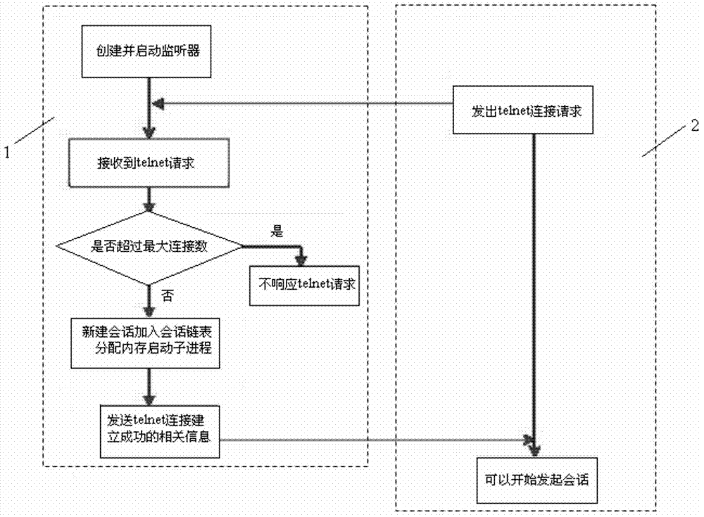
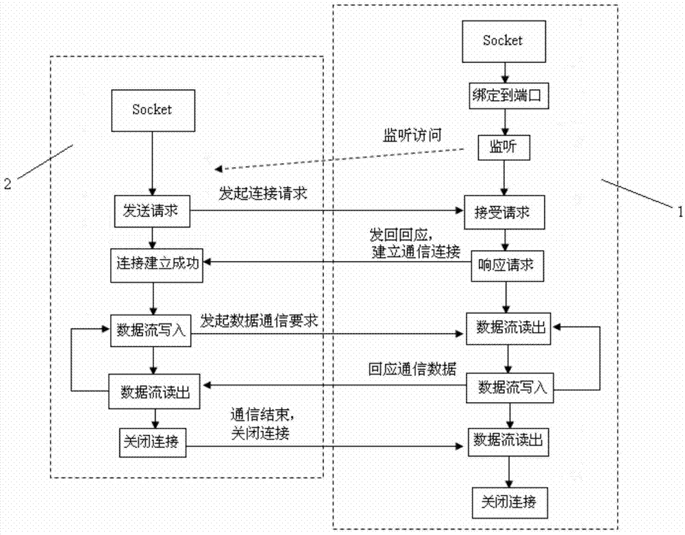
technical field [0001] The invention relates to the field of communication product testing, in particular to a testing method for the maximum number of telnet users supported by switches. Background technique [0002] Telnet protocol is a simple remote terminal protocol in the TCP / IP protocol family. It is the standard protocol and main method of Internet remote login service. Its function is to realize the remote management function. The local computer uses the telnet program to connect to the server, the user enters commands in the telnet program, and the server performs related operations according to the commands, thereby realizing the management and control of the server by the local computer. [0003] The establishment of the telnet connection is mainly realized through the client / server method. The flow chart of the establishment of the telnet connection is as follows: figure 1 As shown: step 1), telnet server 1 creates and enables the TCP listener to listen to the p...

Claims


Application Information

Patent Timeline
Patent Type & Authority Applications(China)
IPC IPC(8): H04L12/26H04L29/06
Inventor 欧春霞
Owner 宋易霄
Learn More