Spring seat for push rod assembly of high pressure pump and high pressure pump

A spring seat, high pressure pump technology, applied in the direction of pumps, multi-cylinder pumps, fuel injection pumps, etc., can solve the problems of spring seat spring seat breakage, achieve uniform elastic deformation, and improve loading efficiency.

Inactive Publication Date: 2016-10-12
ROBERT BOSCH GMBH
View PDF7 Cites 0 Cited by
  • Summary
  • Abstract
  • Description
  • Claims
  • Application Information

AI Technical Summary

Problems solved by technology

In addition to the occurrence of undesired noise this can lead to an overload of the spring seat which in turn can lead to a fracture of the spring seat

Method used


Image

  • Spring seat for push rod assembly of high pressure pump and high pressure pump
  • Spring seat for push rod assembly of high pressure pump and high pressure pump
  • Spring seat for push rod assembly of high pressure pump and high pressure pump

Examples


Embodiment Construction

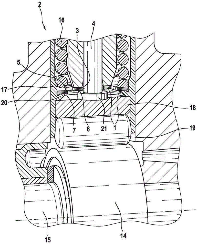
[0030] figure 1 The high-pressure pump according to the invention shown in the middle section comprises at least one pump part with a reciprocatingly guided pump piston 4 , which is supported via a push rod assembly 2 on a cam 14 of a drive shaft 15 . The push rod assembly 2 converts the rotational movement of the drive shaft 15 into a translational movement of the pump piston 4 . The push rod assembly 2 comprises a sleeve-shaped push rod body 17 and a support 18 accommodated therein, in which a roller 191 is rotatably mounted. The push rod assembly 2 abuts against the outer circumferential side of the cam 14 of the drive shaft 15 by means of a roller 19 . A return spring 16 keeps the push rod assembly 2 in contact with the cam 14 .

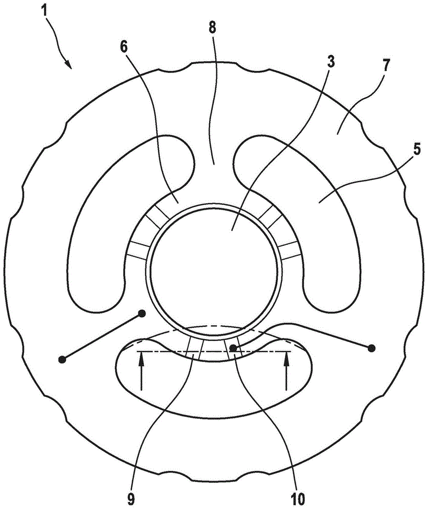
[0031] The sleeve-shaped plunger body 17 has a ring 20 on the inner circumference, on which the support part 18 is supported on the one hand and a spring seat 1 is supported on the other hand. The spring seat 1 has a central bore 3 for receivi...


PUM


Abstract

The invention relates to a spring washer for a plunger assembly (2) of a high pressure pump in a fuel injection system, wherein the spring washer (1) particularly has a bending punched part and a central recess (3) for receiving a pump piston (4). According to the invention, the spring washer (1) furthermore has at least two crescent-shaped recesses (5) arranged around the central recess (3) that form one support ring (6) located radially inside and one support ring (7) radially outside, which support rings are connected to one another by substantially radial webs (8), wherein the support ring (6) located radially inside has regions (9, 10), which are raised and lowered relative to a plane (E) and which are each arranged at an angle spacing to the substantially radial webs (8). The invention further relates to a high pressure pump for a fuel injection system having such a spring washer (1).

Description

technical field [0001] The present invention relates to spring seats. The invention also relates to a high-pressure pump with such a spring seat. Background technique [0002] A spring seat of the above-mentioned type or a high-pressure pump with such a spring seat is known, for example, from laid-open document DE 103 55 027 A1. The high-pressure pump described therein has at least one pump part with a pump piston that delimits a pump working chamber and can be driven to and fro at least indirectly via a drive shaft against the force of a return spring. For this purpose, the pump piston is supported indirectly on the drive shaft via a sleeve-shaped plunger. To connect the pump piston to the push rod, a spring seat is provided, which catches the piston foot of the pump piston behind it. The push rod and the pump piston are kept in contact with the drive shaft by the return spring supported on the spring seat. [0003] The push rod has a radially inwardly extending ring, o...

Claims


Application Information

Patent Timeline
Patent Type & Authority Patents(China)
IPC IPC(8): F04B1/04F02M59/06F02M59/10F02M59/44
CPCF02M59/06F02M59/102F04B1/0426F04B1/0435F04B1/0439
Inventor E·迈尔G·迈尔M·孔茨F·肖尔茨
Owner ROBERT BOSCH GMBH
Why Eureka
Try Eureka