Connecting rod fine boring fixture

A technology of fine boring and connecting rod, which is applied in the field of boring fixtures, can solve problems such as affecting the positioning and machining accuracy of connecting rods, and reducing the machining accuracy.

Active Publication Date: 2014-01-08
LIUZHOU MINGYU MACHINERY
View PDF5 Cites 46 Cited by
  • Summary
  • Abstract
  • Description
  • Claims
  • Application Information

AI Technical Summary

Problems solved by technology

This connecting rod fine boring fixture has the following deficiencies in the use process: 1. When the small head of the connecting rod is auxiliary clamped, tightening the compression screw will generate a small amount of force in the tangential direction of the compression screw, making the connecting rod The small head produces a small amount of elastic deformation. After the boring is completed and the connecting rod is removed, the deformation rebounds, and the processing accuracy will be reduced; 2. Since the compression screw and the strap are connected by threads, there is a certain gap between the internal and external threads. , affecting the positioning and processing accuracy of the connecting rod, especially the parallelism between the big and small head holes of the connecting rod, the pass rate of the parallelism accuracy between the big and small head holes of the connecting rod is 75%

Method used


Image

  • Connecting rod fine boring fixture
  • Connecting rod fine boring fixture
  • Connecting rod fine boring fixture

Examples


Embodiment Construction

[0015] The present invention will be described in further detail below in conjunction with accompanying drawing embodiment:

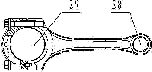
[0016] Such as figure 1 Shown is the connecting rod that needs to be clamped and positioned in this embodiment, and the big head hole 29 and the small head hole 28 of the connecting rod are the holes that need to be fine-bored.

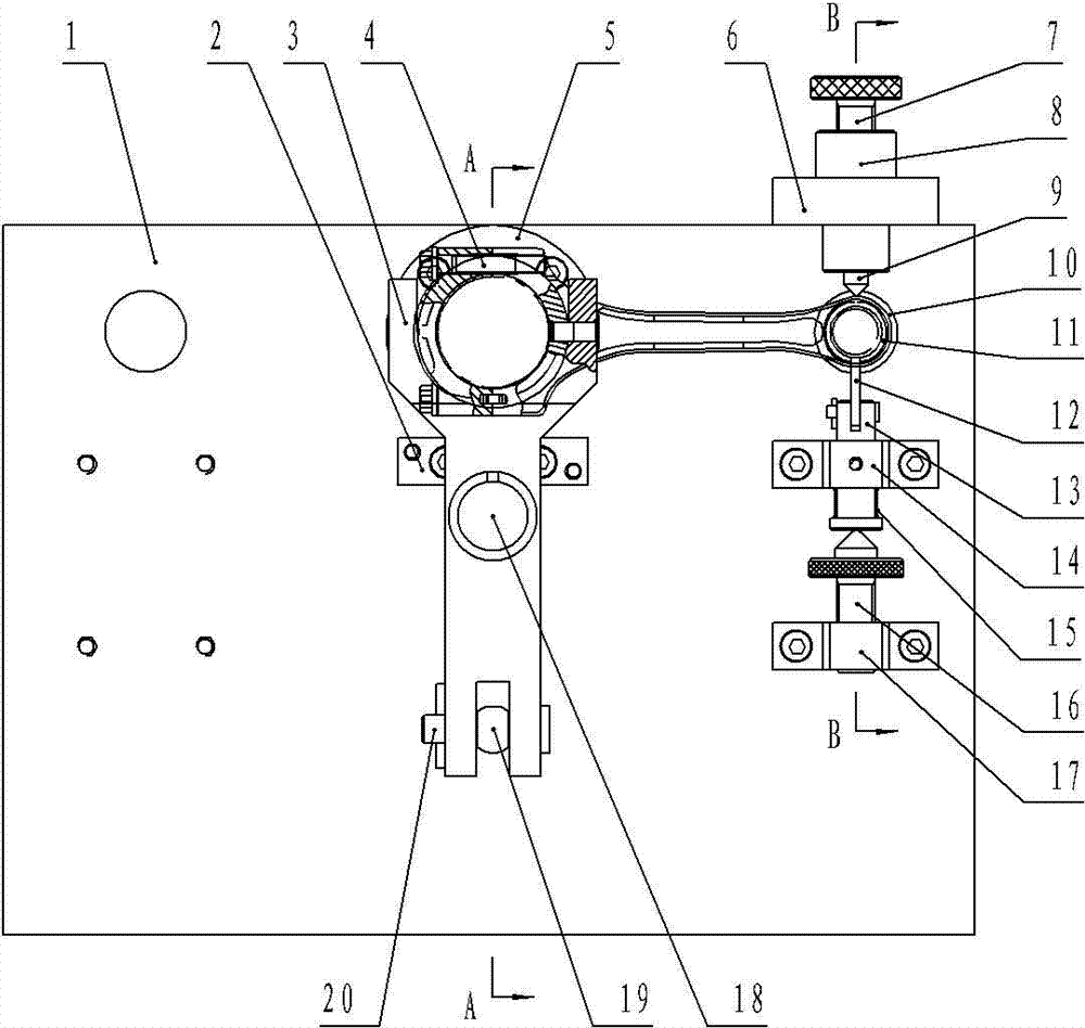
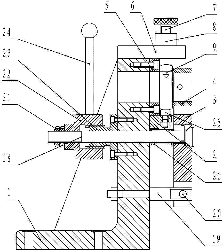
[0017] Such as figure 2 , image 3 , Figure 4 The shown connecting rod fine boring jig includes a clamp body 1 with a support plate, on which a large head positioning device and a positioning mandrel 11 are movable, and the positioning mandrel 11 passes through the positioning guide sleeve 10 It is worn on the support plate, and the support plate is equipped with a pressing device near the big head positioning device, and the upper and lower sides of the positioning mandrel 11 are respectively equipped with a cone support device and a V-shaped support device. The strap 6 at the upper end of the support plate and the pin s...


PUM


Abstract

The invention discloses a connecting rod fine boring fixture, and relates to the technical field of machining process devices. The connecting rod fine boring fixture comprises a fixture body provided with a supporting plate portion, wherein a large head positioning device and a positioning mandrel are arranged on the supporting plate portion, a pressing device is arranged close to the large head positioning device, a conical head supporting device and a V-shaped supporting device are arranged on the upper side of the positioning mandrel and the lower side of the positioning mandrel respectively, the conical head supporting device comprises a butt strap which is arranged at the upper end of the supporting plate portion, and a pin sleeve which is arranged on the butt strap in a penetrating mode and provided with a limiting hole, a pressing screw with the upper portion extending out of the upper end face of the pin sleeve of the conical head supporting pin and a conical head supporting pin which is connected with the pressing screw in a butt joint mode are sequentially connected to the pin sleeve from top to bottom, the conical head supporting pin is clamped in the limiting hole of the pin sleeve through a first spring, and the lower portion of the conical head supporting pin extends out of the lower end face of the pin sleeve of the conical head supporting pin. Compared with the prior art, the connecting rod fine boring fixture has the advantages that the pressing screw drives the conical head supporting pin to move up and down, and therefore the influences of small force generated in the tangential direction of the pressing screw and thread fit clearance on clamping accuracy and positioning accuracy are eliminated.

Description

technical field [0001] The invention relates to the technical field of mechanical processing equipment manufacturing, in particular to a boring jig used for fine boring large and small head holes of connecting rods. Background technique [0002] The process of fine boring the large and small head holes of the connecting rod is one of the key processes in the processing of the connecting rod, and it is the guarantee to determine whether the size accuracy and position accuracy of the large and small head holes of the connecting rod meet the design requirements; usually in the large and small connecting rod When the head hole is fine-bored, a fixture must be used to position and clamp the connecting rod. There is a connecting rod fine boring fixture. The connecting rod fine boring fixture includes a clamp body with a seat plate and a support plate connected to the seat plate. The support plate is fixed with a big head positioning device and A positioning mandrel is movable, an...

Claims


Application Information

Patent Timeline
Patent Type & Authority Applications(China)
IPC IPC(8): B23Q3/06
CPCB23Q3/062
Inventor 叶显旺
Owner LIUZHOU MINGYU MACHINERY
Why Eureka
Try Eureka