Three-freedom-degree parallel mechanism

A degree of freedom and parallel technology, applied in the direction of manipulators, program-controlled manipulators, metal processing machinery parts, etc., can solve problems such as difficult control and calibration, complex kinematic models, etc., and achieve the effect of easy motion control, simple structure and high rigidity

Active Publication Date: 2014-01-08
ZHEJIANG SCI-TECH UNIV
View PDF10 Cites 5 Cited by
  • Summary
  • Abstract
  • Description
  • Claims
  • Application Information

AI Technical Summary

Problems solved by technology

[0004] Existing two-transfer-one-transfer three-degree-of-freedom parallel mechanisms, such as: US6431802, CA2349576, ZL200610013608.3, ES59905578D, etc., have complex kinematic models and difficult control and calibration problems

Method used


Image

  • Three-freedom-degree parallel mechanism
  • Three-freedom-degree parallel mechanism
  • Three-freedom-degree parallel mechanism

Examples


Embodiment 1

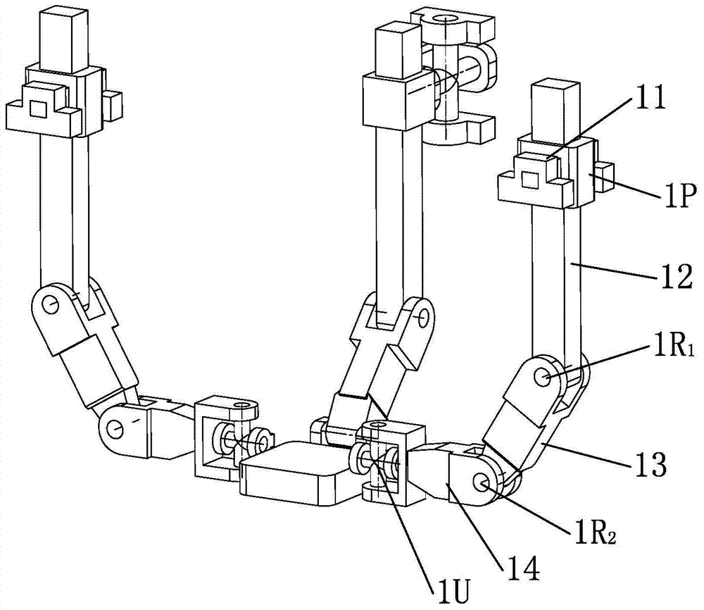
[0020] Example 1 as figure 1 As shown, this embodiment is a three-degree-of-freedom parallel mechanism, including a frame (composed of two first frames 11 and a third frame 31), a moving platform 4, and three branches connecting the frame and the moving platform . Among them, the third branch sequentially includes the universal hinge 3U, the moving pair 3P (composed of the guide rod 33 and the slider 32), the guide rod 33, the first rotating pair 3R 1 , connecting rod 34, second revolving pair 3R 2 ; The first branch and the second branch are arranged symmetrically to the moving platform, and respectively include the moving pair 1P, the guide rod 12, and the first rotating pair 1R in sequence 1 , the first connecting rod 13, the second rotating pair 1R 2 , the second connecting rod 14 and the universal hinge 1U; in the first branch: the axis of the moving pair 1P is perpendicular to the first rotating pair 1R 1 , the second revolving pair 1R 2 The axes of the two rotating...

Embodiment 2

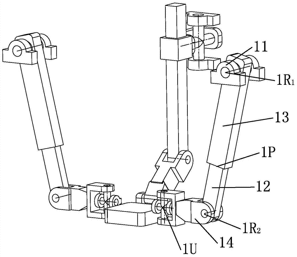
[0021] Example 2 as figure 2 As shown, this embodiment is also a three-degree-of-freedom parallel mechanism, including a frame (composed of two first frames 11 and a third frame 31), a moving platform 4, and three connecting frames and moving platforms. branch. Among them, the third branch sequentially includes the universal hinge 3U, the moving pair 3P (composed of the guide rod 33 and the slider 32), the guide rod 33, the first rotating pair 3R 1 , connecting rod 34, second revolving pair 3R 2 ; The first branch and the second branch are arranged symmetrically to the moving platform, and respectively include the first revolving pair 1R in turn 1 , moving pair 13, guide rod 1P, second rotating pair 1R 2 , connecting rod 14 and universal hinge 1U. In the first branch: the axis of the moving pair 1P is perpendicular to the first rotating pair 1R 1 , the second revolving pair 1R 2 The axes of the two rotating pairs in the universal joint 1U are always perpendicular to the...

Embodiment 3

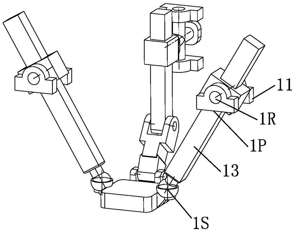
[0022] Example 3 as image 3 As shown, this embodiment is also a three-degree-of-freedom parallel mechanism, including a frame (composed of two first frames 11 and a third frame 31), a moving platform 4, and three connecting frames and moving platforms. branch. Among them, the third branch sequentially includes the universal hinge 3U, the moving pair 3P (composed of the guide rod 33 and the slider 32), the guide rod 33, the first rotating pair 3R 1 , connecting rod 34, second revolving pair 3R 2 ; The first branch and the second branch are arranged symmetrically to the moving platform, and respectively include the rotating pair 1R, the first connecting rod 13 , the moving pair 1P, the guide rod 12 and the ball joint 1S. In the first branch: the axis of the moving pair 1P is perpendicular to the axis of the rotating pair 1R, and the second branch is the same as the first branch. In the third branch: the axis of the horizontal rotary joint in the universal joint 3U and the fi...


PUM


Abstract

The invention relates to a three-freedom-degree parallel mechanism. The three-freedom-degree parallel mechanism has the advantages of being simple in structure, high in rigidity, convenient to manufacture and install and capable of easily achieving motion control. According to the technical scheme, the three-freedom-degree parallel mechanism comprises a rack, a movable platform and three branches connected between the rack and the movable platform, wherein the first branch and the second branch are symmetric to the movable platform, and the third branch sequentially comprises a universal hinge, a sliding pair, a guide rod, a first rotating pair, a connecting rod and a second rotating pair. The three-freedom-degree parallel mechanism is characterized in that the first branch and the second branch respectively and sequentially comprise a sliding pair, a guide rod, a first rotating pair, a first connecting rod, a second rotating pair, a second connecting rod and a universal hinge or respectively and sequentially comprise a first rotating pair, a sliding pair, a guide rod, a second rotating pair, a connecting rod and a universal hinge or respectively and sequentially comprise a rotating pair, a first connecting rod, a sliding pair, a guide rod and a spherical hinge or respectively and sequentially comprise a sliding pair, a guide rod, a first rotating pair, a first connecting rod and a spherical hinge.

Description

technical field [0001] The invention relates to a robot mechanism, in particular a three-degree-of-freedom parallel mechanism capable of realizing two rotations and one movement. Background technique [0002] Since the successful application of Steward mechanism in tire testing and flight simulators, parallel mechanism has been the research object of many scholars. Compared with the traditional serial mechanism, the parallel mechanism (PM) has greater stiffness, load and higher precision. In a certain sense, the parallel mechanism has the advantages of CNC machine tools (high rigidity, high precision, high speed) and industrial robots (low cost, flexibility, and easy integration). However, the complex operation of parallel mechanisms, especially multi-degree-of-freedom parallel mechanisms, is a major problem. Therefore, finding a parallel mechanism with few degrees of freedom that can realize corresponding operations can effectively simplify calculations, control and reduce...

Claims


Application Information

Patent Timeline
Patent Type & Authority Applications(China)
IPC IPC(8): B25J9/00B23Q1/64
Inventor 李秦川吴伟峰陈巧红
Owner ZHEJIANG SCI-TECH UNIV
Why Eureka
Try Eureka