Feeding device with drying function

A technology of feeding device and drying function, which is applied in the field of feeding device with drying function, can solve the problems of plastic extruder cutting and idling, materials sticking into lumps, and difficulty in feeding, so as to ensure normal operation and maintain The effect of dryness

Inactive Publication Date: 2014-01-08
昆山市华浦塑业有限公司
View PDF3 Cites 4 Cited by
  • Summary
  • Abstract
  • Description
  • Claims
  • Application Information

AI Technical Summary

Problems solved by technology

Generally, plastic granules are dried to varying degrees before being added to the feeding hopper, and the dried materials are accumulated and stored in the feeding hopper, and it usually takes a while before they are sent into the extruder. During this process, most of the material is in contact with the air and absorbs moisture in the air, so that the dryness of the material when it enters the extruder is different from the expected dryness, which will easily reduce the surface quality of the extruded plastic. affected
[0003] Moreover, the above-mentioned feeding method is likely to cause material blockage at the outlet of the feeding hopper, forming a "bridging" phenomenon, which in turn affects the normal feeding of the feeding hopper, so that the plastic extruder breaks and idles, and production cannot continue. The service life of the screw and barrel of the discharge machine has a great influence, and the manufacturer must equip a special person to stir in the hopper, and the feeding effect fluctuates greatly
However, the existing forced-feeding adopts the spiral downward pressure type, and the screw downward pressure structure is used in the feeding hopper, which not only often gets stuck due to the uneven size of the material, but also consumes a lot of energy during the long-distance screw pressing process. It is easier to cause the temperature in the feeding hopper to rise and make the material sticky and difficult to feed

Method used


Image

  • Feeding device with drying function
  • Feeding device with drying function
  • Feeding device with drying function

Examples


Embodiment Construction

[0021] The technical solutions of the present invention will be further described below in conjunction with the accompanying drawings and through specific implementation methods.

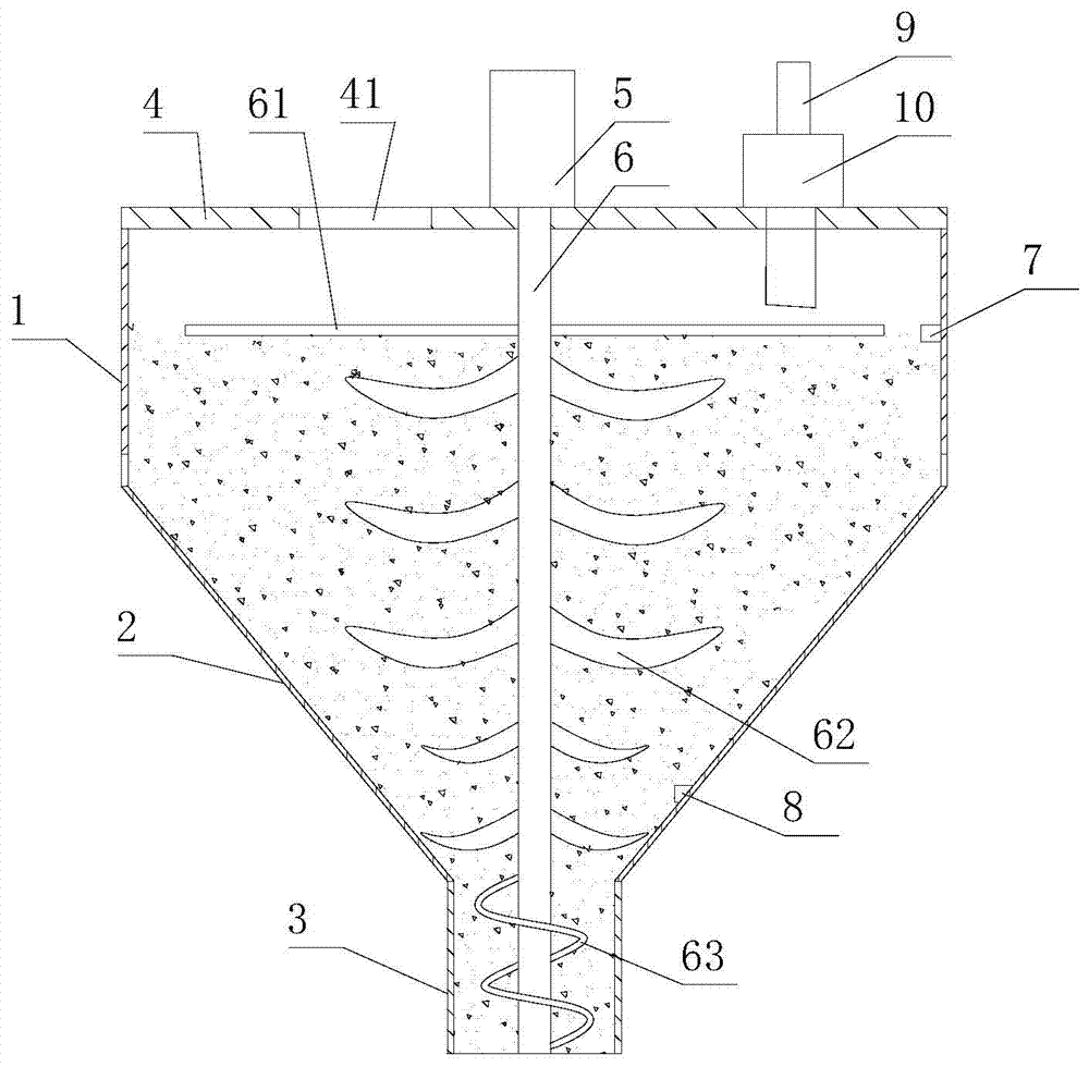
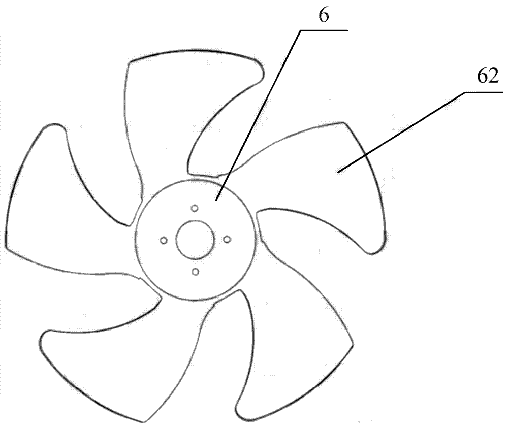
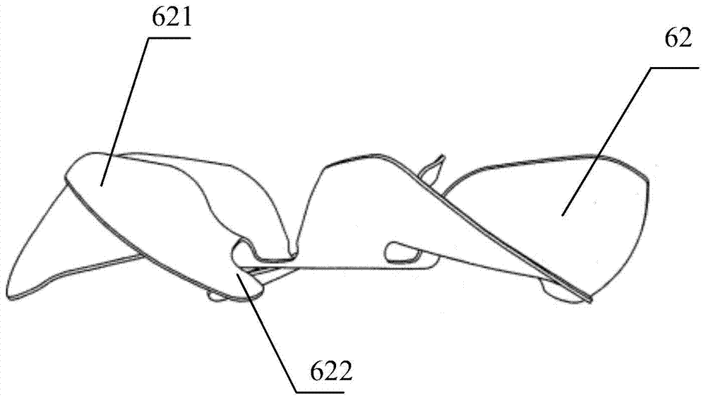
[0022] Such as Figures 1 to 3 As shown, a feeding device with a drying function includes a feeding hopper, and the feeding hopper includes an inverted conical storage section 2 and a circular discharge section 3, the storage section 2 and the discharge section 3 are Coaxial setting; the top of the storage section 2 is provided with a cover plate 4, the cover plate 4 is provided with a feed port 41, the top of the cover plate 4 is provided with a drive motor 5, and the drive motor 5 is connected to a main shaft that extends into the inside of the feeding hopper 6. There are multiple groups of loose blade structures arranged at intervals on the main shaft 6. The loose blade structures are located in the material storage section 2. Each group of loose blade structures includes at least 4 ring-shaped u...


PUM


Abstract

The invention discloses a feeding device with a drying function. The feeding device comprises a feeding hopper, wherein the feeding hopper comprises an inverted-cone-shaped storing section and a ring-shaped discharging section; the storing section and the discharging section are coaxially arranged, the top of the storing section is provided with a cover plate, the cover plate is provided with a feed port, the top of the cover plate is provided with a driving motor, and the driving motor is connected with a main shaft which stretches into the feeding hopper; the main shaft is provided with multiple groups of loose blade structures at intervals, the loose blade structures are positioned in the storing section, each blade structure comprises at least four loose blades which are uniformly distributed in an annular manner, and each loose blade is arranged in an inclined manner; the blade surface of each loose blade is arranged in a manner of facing the rotating direction of the main shaft, the tail end of the main shaft is provided with a helical blade, and the helical blade is arranged in the discharging section; the top of the cover plate is also provided with a material drying device, and the material drying device is communicated with the interior of the feeding hopper. The feeding device with the drying function, provided by the invention, has the advantages that the dryness of a material is kept, and the feed is easy.

Description

technical field [0001] The invention relates to the technical field of extruder equipment, in particular to a feeding device with a drying function. Background technique [0002] The host of the plastic extruder is the extruder, which consists of an extrusion system, a transmission system and a heating and cooling system. At present, the automatic metering system is used for feeding the plastic extruder. The plastic and powder are stored in the large feeding hopper, and the stored material is fed to the extrusion equipment through the automatic metering system. In principle, as long as there is material in the feeding hopper, production can be done. Continuous, so keeping the feed hopper filled is critical. The existing feeding hopper has a large volume, and a large amount of materials can be poured in at one time, and enter into the feeding port of the plastic extruder from top to bottom by utilizing the gravity without power. Generally, plastic granules are dried to vary...

Claims


Application Information

Patent Timeline
Patent Type & Authority Applications(China)
IPC IPC(8): B29C47/10B29C47/78B29C47/92B29C48/793B29C48/92
CPCB29C48/92B29C48/793B29C48/287B29C48/286B29C2948/92333B29C2948/92828B29C2948/92161B29C2948/9279
Inventor 吴镇宇
Owner 昆山市华浦塑业有限公司
Why Eureka
Try Eureka