Traction mechanism for drilling rig towed by drilling rig

A technology of rock drilling rig and traction mechanism, which is applied in earth-moving drilling, mining equipment, tunnels, etc., can solve the problems of easy damage of tensioning rope, labor-intensive and labor-intensive etc.

Active Publication Date: 2015-10-28
CHINA RAILWAY TUNNEL GROUP CO LTD +1
View PDF12 Cites 0 Cited by
  • Summary
  • Abstract
  • Description
  • Claims
  • Application Information

AI Technical Summary

Problems solved by technology

[0003] The purpose of the present invention is to overcome the status quo in the background technology that the tension rope is easily damaged and the replacement process is laborious and laborious. It discloses a new traction mechanism for the rock drilling rig to tow the drilling rig, and provides a tensioning mechanism for the traction mechanism. Rope and how to use it

Method used


Image

  • Traction mechanism for drilling rig towed by drilling rig
  • Traction mechanism for drilling rig towed by drilling rig
  • Traction mechanism for drilling rig towed by drilling rig

Examples


Embodiment 1

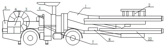
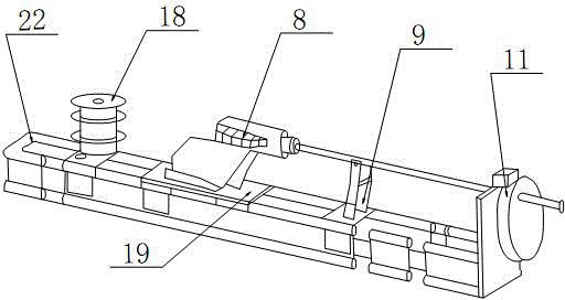
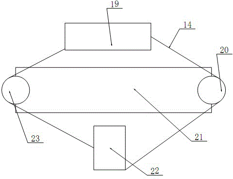
[0021] Embodiment 1: a kind of tension rope and using method for rock drilling jumbo thruster, see Figure 1-4 , the present invention includes a tension rope 14, a front pulley 23, a rear pulley 20, a drilling rig carriage 19 of a rock drilling jumbo and a propulsion beam 22 of the rock drilling jumbo, and the drilling rig carriage 19 is slidably installed on the rock drilling jumbo to propel On the slideway of the device, the front pulley 23 and the rear pulley 20 are respectively fixed on the front and rear ends of the cylinder barrel of the propulsion cylinder 21 in the propeller, and there are two tension ropes 14, which are respectively a traction rope and a return rope, wherein the traction One end of the rope is fixed on the drilling rig pallet 19, the other end is fixed on the propulsion beam 22 of the rock drilling rig around the front pulley 23, one end of the return rope is fixed on the drilling rig pallet 19, and the other end is wound around the rear The pulley 2...

Embodiment 2

[0033] Embodiment 2: the working principle of this embodiment is the same as embodiment 1, and the specific difference is that the tension adjustment mechanism includes a threaded button 15, an adjusting rope 24, an adjusting screw 26, a backing plate 27 and a U-shaped fixed pipe 25, and a threaded button 15 The two ends are respectively fastened and connected with the adjustment rope 24 and the tension rope 14, the bent end of the U-shaped fixed pipe 25 is fixed with the adjustment rope 24, and its open end is fixed in the backing plate 27, and the backing plate 27 is penetrated by the adjustment screw 26 And the advancing beam 22 is fixed on the advancing beam 22, and the length of the stud part of the adjusting screw 26 is not less than the sum of the thickness of the backing plate and the length of the screw hole.

[0034]When working, one end of the adjustment rope 24 is fixed with the tension rope through a threaded buckle, and after the other end is wound and fixed with ...


PUM


Abstract

The invention relates to a hauling mechanism for a drill jumbo to pull a drilling machine to walk. The problems that a tensioning rope can be damaged easily, and work and labor are consumed in the replacing process in the background technology are solved. The structural design and application method of the hauling mechanism of a propeller of the hydraulic drill jumbo are disclosed. According to the hauling mechanism for the drill jumbo to pull the drilling machine to walk, a tensioning rope is fixed with a drilling machine carriage through a hanging ring, the other end of a hauling rope sequentially passes through a screw thread and an adjusting screw rod and is fixedly connected with a propelling beam, one end of the screw thread is fixedly connected with the tensioning rope, the other end of the screw thread is in screw-threaded fit with the adjusting screw rod, the adjusting screw rod is mounted on the propelling beam of the drill jumbo, and an adjusting screw nut is fixedly arranged on the adjusting screw rod. The structure is simple, operating is easy, dismounting and mounting are extremely convenient, the tensioning rope can be repeatedly used, safety and reliability are achieved, time and labor are saved, abrasion resistance is improved, working efficiency is greatly improved, and service life is prolonged.

Description

technical field [0001] The invention relates to a traction mechanism, in particular to a traction mechanism for a drilling rig to be driven by a rock drilling jumbo. Background technique [0002] At present, more and more hydraulic rock drilling rigs are used in the construction of underground tunnel engineering by drilling and blasting. Walk up to complete the feeding function of drilling. But the traction and tension rope on the rock drilling jumbo is not only complex in structure, but also has the problems of extremely inconvenient disassembly, easy damage, and high failure rate. The front end of the original traction tensioning rope is a 210mm long screw rod. When the drilling rig is running, it relies on the rotation of the front pulley to drive the traction tensioning rope to travel. During the running process of the drilling rig, the screw rod often turns into the front pulley, causing the screw rod to bend and deform, which is easy to be damaged; The adjusting scre...

Claims


Application Information

Patent Timeline
Patent Type & Authority Patents(China)
IPC IPC(8): E21D9/10
Inventor 张培聪胡卫平张毅燃张定勇
Owner CHINA RAILWAY TUNNEL GROUP CO LTD
Why Eureka
Try Eureka