Capacitive ignition device with speed limit and easy start functions

An ignition device, capacitive technology, applied in the direction of a capacitor energy storage device, etc., can solve problems such as difficulty in starting the engine, difficulty in starting at low speed, small change in the ignition angle of the igniter, etc. Solving startability problems, effect of ignition timing

Active Publication Date: 2014-01-08
ZHENGJIANG FENGLONG ELECTRIC CO LTD
View PDF5 Cites 2 Cited by
  • Summary
  • Abstract
  • Description
  • Claims
  • Application Information

AI Technical Summary

Problems solved by technology

[0002] With the development of gasoline engine ignition module technology, the existing ignition devices for small gasoline engines such as lawn mowers, chain saws, blowers, etc. generally have low-speed start-up difficulties, high-speed overspeed and speeding phenomenon, which has always been an important technology in the field of small gasoline engines. Difficulties; and during the working process, the ignition angle of the igniter in the ignition device changes little, and it cannot guarantee that the ignition can be ignited at the best ignition point at any speed, resulting in difficulty in starting the engine, and the engine output power is small at certain speeds. The fuel consumption of the engine is high, the emission exceeds the standard, pollutes the environment, and does not comply with environmental protection laws

Method used


Image

  • Capacitive ignition device with speed limit and easy start functions
  • Capacitive ignition device with speed limit and easy start functions
  • Capacitive ignition device with speed limit and easy start functions

Examples


Embodiment Construction

[0016] In order to enable those skilled in the art to better understand the solutions of the present invention, the technical solutions in the embodiments of the present invention will be clearly and completely described below in conjunction with the drawings in the embodiments of the present invention.

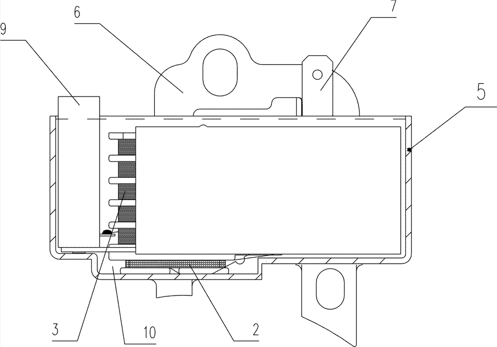
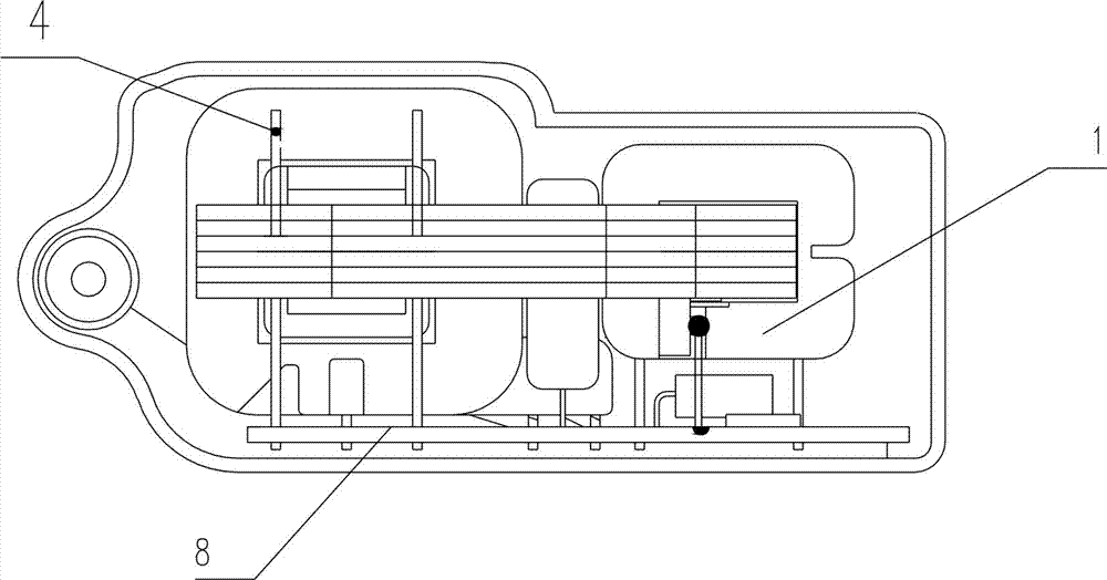
[0017] Such as figure 1 , 2 Shown is a schematic diagram of the external mechanical structure of the present invention, a capacitive ignition device with speed limiting and easy-to-start functions, including a charging coil 1, a trigger coil 2, a secondary coil 3, a primary coil 4, a casing 5, and an iron core 6 , flame extinguishing sheet 7, circuit board 8, terminal post 9 (high-voltage line lead-out) and epoxy resin 10 filled in the space in the shell 5.

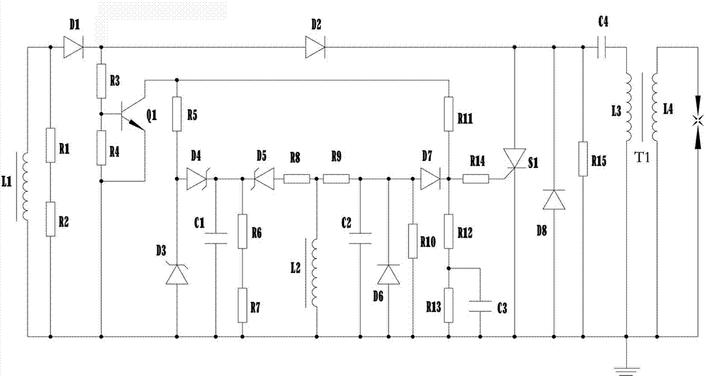
[0018] Such as image 3 As shown, a capacitive ignition device with speed-limiting and easy-start functions includes a charging circuit for charging the ignition capacitor, which includes a charging coil L1, diodes D1,...


PUM


Abstract

The invention discloses a capacitive ignition device with speed limit and easy start functions. The capacitive ignition device comprises a charging circuit, a silicon controlled rectifier S1, a triggering circuit, a speed limit circuit and an ignition coil T1. The charging circuit is used for charging an ignition capacitor and comprises a charging coil L1, a diode D1, a diode D2 and the ignition capacitor C4; the silicon controlled rectifier S1 is used for controlling the ignition capacitor C4 to be charged or discharged, the cathode of the silicon controlled rectifier S1 is grounded, and the anode of the silicon controlled rectifier S1 is connected to the input end of the ignition capacitor C4; the triggering circuit is used for control the discharging time of the ignition capacitor C4, is connected with a control electrode of the silicon controlled rectifier S1 and controls connection and cut-off of the silicon controlled rectifier S1; the speed limit circuit is used for controlling the discharging time of the ignition capacitor C4 in high-speed running, is connected with the control electrode of the silicon controlled rectifier S1 and controls the connection and cut-off of the silicon controlled rectifier S1; the ignition coil T1 comprises a primary coil L3 and a secondary coil L4, and the secondary coil L4 outputs high voltage. The capacitive ignition device is stable in circuit, solves the problem of the startability of a cold engine and avoids the phenomena of high speed, overspeed and galloping.

Description

technical field [0001] The invention relates to the field of an ignition device for a small gasoline engine, in particular to a capacitive ignition device with speed limiting and easy-start functions. Background technique [0002] With the development of gasoline engine ignition module technology, the existing ignition devices for small gasoline engines such as lawn mowers, chain saws, blowers, etc. generally have low-speed start-up difficulties, high-speed overspeed and speeding phenomena, and have always been an important technology in the field of small gasoline engines. Difficulties; and during the working process, the ignition angle of the igniter in the ignition device changes little, and it cannot guarantee that the ignition can be ignited at the best ignition point at any speed, resulting in difficulty in starting the engine, and the engine output power is small at certain speeds. The fuel consumption of the engine is high, the emission exceeds the standard, pollutes...

Claims


Application Information

Patent Timeline
Patent Type & Authority Applications(China)
IPC IPC(8): F02P3/08
Inventor 张斌李江邓大海郑梅君
Owner ZHENGJIANG FENGLONG ELECTRIC CO LTD
Why Eureka
Try Eureka