Hand rubbing bionic mechanism

A two-handed, frame-based technology, applied to mechanical equipment, transmission devices, belts/chains/gears, etc., can solve the problems of high cost, complex structure, high cost, etc., and achieve wide popularization and use, high work reliability, and low cost Effect

Inactive Publication Date: 2016-08-17
SUZHOU ROARING PRECISION MASCH CO LTD
View PDF7 Cites 0 Cited by
  • Summary
  • Abstract
  • Description
  • Claims
  • Application Information

AI Technical Summary

Problems solved by technology

This not only makes the whole device extremely large and complex, but also extremely expensive
For example, the kneading massager disclosed in Chinese patent document CN 102940566 A is not only extremely complicated in structure, but also fails to give the trajectory of bionic motion; another example is the numerically controlled rubbing type grinding machine disclosed in Chinese patent document CN 103252709 A, which uses three servo The motor, as well as the extremely complex mechanical transmission system, is bulky and expensive
From the perspective of kinematics, no substantial hands-rubbing bionic mechanism has been retrieved so far

Method used


Image

  • Hand rubbing bionic mechanism
  • Hand rubbing bionic mechanism
  • Hand rubbing bionic mechanism

Examples


Embodiment 1

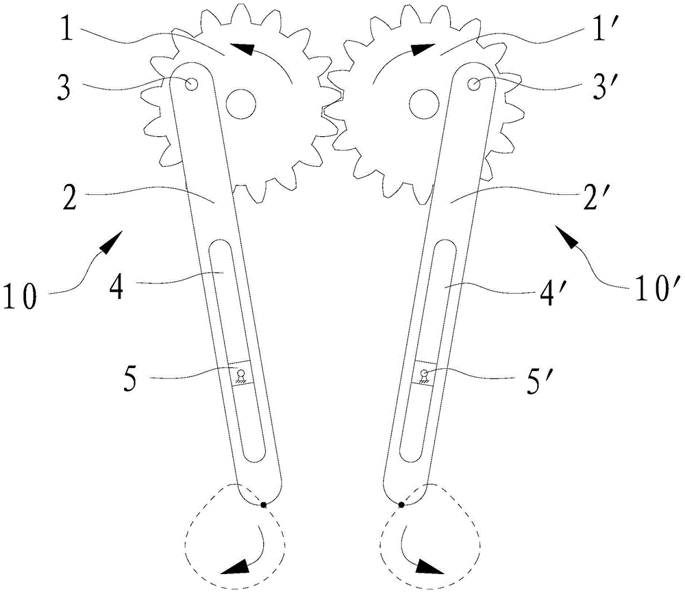
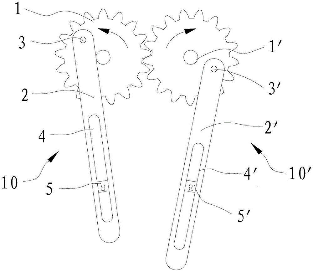
[0021] see picture 1 ,picture 2 The bionic mechanism for hands rubbing shown includes a frame (not shown in the figure), two sets of rubbing components arranged on the frame 10 、 10 ’。

[0022] kneading components 10 Consists of gears rotatably arranged on the frame around the axis 1 , through the pin 3 rotatably set on the gear 1 connecting rod 2 . gear 1 There is an eccentric pin hole on the top, the center line of the pin hole is parallel to the gear 1 axis, pin 3 one end connected to the connecting rod 2 The upper part, the other end of which is rotatably passed through the above-mentioned pin hole. link 2 There is a chute on the top 4 , the chute 4 along the connecting rod 2 Extending in the length direction, the frame is provided with a central hinge on the frame to provide linkage 2 guide slider 5 , the slider 5 The center position of the two axial ends of the hinge is hinged on the frame, and the slider 5 ...

Embodiment 2

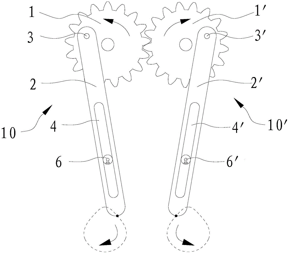
[0031] see picture 3 Shown both hands rubs the bionic mechanism, this bionic mechanism and embodiment 1 The difference is mainly in the provision of connecting rod 2 、 2 ’ Guided component settings. In this embodiment, a connecting rod is provided 2 、 2 ’ Guided parts are centrally fixed guides on the frame 6 、 6 ’, the guide 6 、 6 ’ respectively set in the chute with clearance fit 4 、 4 ’, the guide 6、 6 ’ up and chute 4 、 4 The circumferential outer surface matched with the groove wall in the length direction is a cylindrical surface, and the guide piece 6 、 6 ’ respectively with chute 4 、 4 ’ to form a plane high pair. When the external drive mechanism drives the gear 1 ,gear 1 ’ When one of the gears rotates, the connecting rod 2 、 2 ’ respectively on the pin 3 、 3 ’ under the action of the guide relative to the cylindrical outer surface 6 、 6 ’Does both linear motion and swing, so that the connecting rod 2 、 2 ’...


PUM


Abstract

The invention discloses a bionic mechanism for hands rubbing, which comprises a frame and two sets of rubbing components arranged on the frame, and each group of rubbing components includes a gear, a connecting rod, a slider whose center is hinged on the frame or a center fixed on the frame. The guide piece on the cylindrical outer surface on the frame, the connecting rod is provided with a chute extending along its length, and the slider or the guide piece are arranged in the chute with clearance fit to provide the guide of the connecting rod. The two gears on the components are engaged. When the external drive mechanism drives the gears on one set of kneading components to rotate, the lower ends of the upper connecting rods of the two sets of kneading components will produce a bionic movement similar to hands kneading. The bionic mechanism realizes the complex planar movement imitating the rubbing of human hands with fewer parts. Its structure is extremely simple, the cost is particularly low, and the work reliability is high. It can meet the requirements of various corresponding products for rubbing hands at a very low cost. Institutional needs, with good practicality.

Description

technical field [0001] The invention relates to a bionic mechanism for rubbing hands. Background technique [0002] In the innovative design of the mechanism, it is extremely difficult to imitate the movement of human hands by relying solely on the movement of the mechanism itself. Because the movement of human hands rubbing is a compound motion of linear motion and swing. Using numerical control technology to imitate the action of human rubbing is the easiest technical solution to think of. However, using numerical control technology to imitate the movement of rubbing with one hand requires at least two servo motors, which are programmed and driven by a two-axis linkage numerical control system; system control to achieve. This not only causes the whole device to be extremely large and complex, but also extremely expensive. For example, the kneading massager disclosed in Chinese patent document CN 102940566 A is not only extremely complicated in structure, but also fails...

Claims


Application Information

Patent Timeline
Patent Type & Authority Patents(China)
IPC IPC(8): F16H37/12
CPCF16H37/122F16H37/126
Inventor 窦云霞王传洋钟康民
Owner SUZHOU ROARING PRECISION MASCH CO LTD
Why Eureka
Try Eureka